

The AS-1 DAC from Audio-gd is a very straightforward looking component that uses high-quality parts and interesting circuit design to achieve a high level of measured performance with very low distortion.
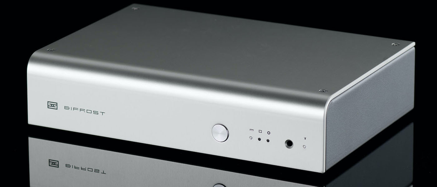
Audio-gd AS-1 DAC
- Simple black box with quality parts and a fully balanced design inside.
- Dual ESS Sabre PRO DAC chips are managed with an FPGA.
- Clean and transparent sound quality with plenty of detail.
- The company has a reputation for high-value products and AS-1 is no different.
- The direct online sales model keeps prices reasonable.
- DAC can decode almost anything but I wish the display screen gave more information.

Audio-gd is a Chinese audio component manufacturer that produces a variety of core audio gear including DACs, preamps, and power amps. They focus on producing high-quality audio products with a minimum of external “bling”. While they do work with distributors in various countries, in North America, sales are managed directly over the internet. This helps keep prices approachable for gear that might otherwise cost much more. Audio-gd has developed quite an online following, particularly for their headphone amps and DACs. I used to own one of their now discontinued Compass 2 model DAC/headphone amps, and I remember it for having a warm and pleasing character to its tone that worked well with a variety of headphones. Reading through their website and product descriptions, it becomes apparent that the gear they produce is voiced to meet a preferred “house” sound. One of the ways this is achieved is by manipulating the amounts of second and third-order harmonic distortion that is allowed in the final output. This directly affects how our ears and brain interpret if an audio component sounds tonally “warm” or “smooth” or “clinical” among other audiophile descriptors that we’ve all heard before. It’s part of the reason why tube amps and turntables, for example, sound appealing to a lot of folks. It’s the higher levels of 2nd order (also known as even order) harmonic distortion in the sound.
What got my attention when I read the description of the AS-1 DAC was how Audio-gd purposely tuned it for ultra-low distortion as opposed to their “house” sound and (according to them) how it may appeal to someone more concerned about measurements. Okay. I’ll bite. It’s no “Secret” (Ha! See what I did there?) that, when it comes to DACs, I prefer something that translates the data as precisely as possible instead of embellishing it. We have other components in the audio chain that do a better job acting as tone controls. And since my colleague Glenn Young already reviewed and found much to like in Audio gd’s HE-1 Vacuum preamplifier, I was curious to see how the company would fare with a different type of component that was designed to run more strictly “by the numbers” so to speak.
Design:
Low distortion, Fully Balanced DAC
DAC Chipset:
Two ESS Sabre ES9028Pro Chips in Mono mode, Managed by an FPGA
Manufacturer Freq. Response:
20 Hz – 20 kHz (TO THE LEFT – 0.1 dB)
Signal to Noise Ratio (SNR):
>120 dB (XLR output)
Total Harmonic Distortion (THD):
0.0002%
Output impedance:
10 ohms
Output Level (Volts):
2.25V (RCA)
4.5V (XLR)
2+2MA (ACSS)
Audio Inputs
Digital S/PDIF coaxial (RCA):
Up to 24-bit 192 kHz PCM
Digital S/PDIF coaxial (BNC):
Up to 24-bit 192 kHz PCM
Optical digital (TosLink):
Up to 24-bit 96 kHz PCM
Digital USB (USB-B):
Up to 32-bit 384 kHz PCM and DSD512
I2S (HDMI):
Up to 32-bit 384 kHz PCM and DSD512
Audio Outputs:
Unbalanced analog RCA
Balanced analog XLR
ACSS (Custom Connector)
Output impedance:
10 ohms
Output Level (Volts):
2.25V (RCA)
4.5V (XLR)
2+2MA (ACSS)
Audio Inputs
Unbalanced analog RCA
Digital S/PDIF coaxial (RCA):
Up to 24-bit 192kHz PCM
Optical digital (TosLink):
Up to 24-bit 192kHz PCM
Digital USB (USB-B):
Up to 32-bit 384 kHz PCM and DSD256
Audio Outputs:
Unbalanced analog RCA
Balanced analog XLR
Operating System Support:
Windows, OSX, Linux
Weight:
11 lbs (5 kg)
Dimensions:
240mm x 360mm x 80mm (W x L x H)
Available Colors:
Black Anodized Aluminum
Accessories:
1 x USB Cable
1 x AC Power Cord
MSRP:
$763.00 USD
$863.00 USD with TCXO upgrade
$963.00 USD for Dual ES9038Pro Version
Website:
Company:
SECRETS Tags:
audio-gd, dac, sabre, balanced, DAC Review 2020


The exterior design of the AS-1 is devoid of any frills as it is a straightforward black anodized aluminum case with rounded corners and air vents on top. A very simple, yet sturdy structure model that repeats itself in various other dimensions throughout Audio-gd’s product line. The casework resists scuffing and protects the all-important internals well enough. It certainly isn’t flashy, but I don’t think that is the point. Looking at the front face of the AS-1, we have the power button on the left and then a basic 3-digit blue LED display in the middle with a “Setting” and two “Selector” buttons below that. The LED display reminds me of a digital clock/radio as it mainly shows 3 numbers that correspond to a different input and digital filter states that you can choose from. It’s a slightly arcane system. The left digit displays which of the 7 available PCM digital filters you are using, while the middle digit does the same for the 4 available DSD filters. The right digit on the display indicates what input you have selected, by number only. The inputs on the backside are all numbered accordingly if you need to peek back there just to confirm what input you’ve actually chosen. These settings are all cycled through and selected by those three buttons under the display.

The display itself is my biggest gripe with the Audio-gd AS-1. It’s too basic. The AS-1 can pretty much play any digital signal one can throw at it, but the display doesn’t even tell me what the incoming bit rate or sampling frequency of that signal is. I am left to assume and trust that the AS-1 is decoding a 24/192 or a DSD256 sound file that I am sending its way because I am hearing the sound. Even a bank of simple LED lights with the sampling frequency screen printed on the front face would be helpful. I generally prefer my DACs to give me more information about what they’re doing, not less.

At the back end of the AS-1, we have a full complement of digital inputs consisting of coaxial SPDIF, BNC, optical, i2S via an HDMI connector, and Asynchronous USB. The HDMI connector is pinned to accept i2S data via the same standard that PS Audio follows. The USB input module is made by Amanero and an ASIO and WASAPI driver package for Windows 10 is available on the Audio-gd website for download. The audio outputs are comprised of a pair of balanced XLR, a pair of single-ended RCA and a unique pair of connectors called ACSS. The ACSS connectors are part of a claimed no-feedback, current gain signal chain (similar to the old Krell Cast system) and must be used only with other Audio-gd equipment that uses the same connectors.

Looking at the interior of the AS-1 DAC, one can see a fairly clean circuit layout incorporating a substantive power supply with an R-core transformer at the head of the unit. The back half of the board is taken up by the central FPGA (Field Programmable Gate Array) chip that is flanked by the independent left and right channel circuitry, each having its own ESS ES9028PRO DAC chip under a heatsink. Now Audio-gd doesn’t expressly claim that the AS-1 is the lowest distortion DAC on the market. They do tout its performance as being very good and the ES9028PRO chip is known to have those intrinsic characteristics.
Using two (each of the 8-channel chips run in mono mode) managed by the FPGA sets performance expectations fairly high. The AS-1 can even be custom ordered with twin ES9038PRO DAC chips at additional cost and a 15 day lead time. Sitting just above the right channel circuitry is the USB input board and to the left of that is the small vertically oriented i2S input daughter board.


For my review, the Audio-gd AS-1 DAC was primarily used via the USB connection with my Surface 3 PRO tablet. The Surface uses ROON to access all my digital music files via external hard drive and the Qobuz streaming service. The DAC’s output was then sent to a Benchmark HP4 headphone amplifier/preamp and a Benchmark AHB2 power amplifier. Various speakers and headphones were used listening to the AS-1, including the Revel F228Be, Salk Songtower, ELAC Navis ARB51, Focal Stellia, HiFiMAN HE1000v2, and the STAX 007A via its own SRM-700T and SRM-700S amplifiers.
I also used the AS-1 DAC attached to my desktop workstation via USB and using J.River Media Center 26 as the playback software in that application.
Despite the general description on the Audio-gd website intimating that this DAC would best be suited for people who are more concerned about specs and for testing other parts of the audio chain, I found the unit’s subjective sonic performance to be excellent and enjoyable with all sorts of music that I listened to. As I said earlier, my general bias when it comes to DACs is for accuracy over embellishment, so in hindsight, maybe I am the perfect target market for this thing. To my mind, there are other parts of your audio system that can embellish the overall sound more effectively (the speakers and the room having the most significant influence). An ideal DAC (whether internal or external) should completely and transparently reproduce any signal it’s fed to provide the purest source for the downstream components. To that end, the Audio-gd AS-1 performed superbly. The subjective quality of the sound reproduction compared favorably against the Benchmark 3B DAC when level matched and source-switched through a Benchmark HPA4 preamp. Even listening closely with headphones, I had a difficult time establishing any meaningful sonic differences between the two. You’ll get a good indication of the raw performance metrics in the bench test section below, but when it came to musical enjoyment, words like clean, transparent, revealing, and effortless are the best descriptors that I can provide you with. I tried each of the seven individual digital filter settings and found the effects to be very subtle. After some time I stayed with the fast roll-off, linear filter (#1) for all my remaining listening. The four DSD filters were even harder for me to notice any differences so I left that setting at #4 (47 kHz).
Secrets Sponsor
The functional differences of the AS-1 are where someone most likely will decide if this DAC will ultimately be for them. I’ve already touched on the seemingly antiquated 3-digit display system with no bitrate or sampling information. You can argue that it’s not expressly necessary to show such information with programs like ROON or J.River that tell you exactly what the DAC is doing, and I’ve heard arguments that modern displays are an easy way for noise or distortion to enter the DAC’s system. I don’t know how valid such arguments are but I found the lack of a modern display annoying. The other operational quirk I found has less to do with the AS-1 itself and more to do with computer playback software. J.River Media Center and ROON both occasionally had interesting preferences about how they liked to communicate with the DAC’s USB input. The Windows 10 drivers that are used with the Audio-gd DAC have two components, an ASIO driver and a dedicated Amanero WASAPI driver. Each one has slightly different limitations of what maximum bitrates they will accept, particularly when dealing with DSD files. I found that the current version of ROON does not play well with the ASIO driver, as I kept experiencing the occasional click, pop, and sound dropout even when playing 16/44 FLAC files. In my system, ROON was much happier with the WASAPI driver. With that driver, DSD has to be sent to the DAC via DOP and not natively. Regardless, it sounded excellent and no dropouts or stutters were experienced. J.River was uniformly giving me fits with both drivers, that was until I upgraded from Media Center 24 to 26. Once J.River Media Center 26 was installed, playback was consistently smooth with both drivers and I was able to play everything without issue. Playing some of my classical and jazz DSD256 files that I purchased from the NativeDSD website and listening through the STAX 007A Electrostatic headphones and amplifier was an almost religious experience!

Johnny Hartman “I Just Dropped By To Say Hello” Impulse! Records, 1963, 16/44 via Qobuz
When it comes to Jazz vocalists, Johnny Hartman had one of the richest-sounding and most distinct voices ever. The Audio-gd AS-1 did him proper justice by getting the quality of his deep, resonant vocals rendered just right. When listening via headphones, I could make out the subtlest details in his singing and the breaths taken in between the lyrics. “Charade” and “Stairway To The Stars” were particularly great tracks where I could easily hear the ambient sound of the recording studio and all the details of the delicate brushwork on the drums and crisp cymbal play.
“Stairway” also features a superb sounding saxophone that seemed startlingly real, while “Charade” featured outstanding melodic guitar playing by guests Kenny Burrell and Jim Hall. The bitrate may have been child’s play for a DAC like this to handle, but the clarity and neutrality of the decoding are what stood out to me. An intentionally warm or “tube” sounding DAC would have made this already warm and intimate recording sound heavy and overly saccharine.

Manfred Honeck and the Pittsburgh Symphony Orchestra “Shostakovich Symphony No.5” Barber Adagio, Reference Recordings, 2017, DSD256
This is an immensely dynamic orchestral recording with huge swings in intensity and volume. The AS-1 seemed to perfectly interpret everything from the quietest flute passages and string plucks to the vivid bombast of the whole horn section with bass drums pounding away. Everything sounded spatially accurate and well placed along with just being scrupulously clean sounding overall. J.River MC 26 had no problem playing this track natively using the ASIO driver while ROON preferred the WASAPI driver and converting the signal to high bitrate PCM on the fly. Either way sounded outstanding.

Buena Vista Social Club “Buena Vista Social Club” World Circuit/Nonsuch Records, 1997, 16/44 FLAC
This album is a favorite of mine. The musicianship is so good and the instrumentation so layered and dimensional that it’s a good test of a DACs ability to render all the details clearly and intelligibly. “Chan Chan” is one of my favorite songs on this album. There is just layer upon layer of acoustic guitars, electric slide guitar, congas, bongos, maracas, trumpet, and vocals all weaving in and out. The AS-1 DAC keeps all these elements sounding as clear as day.
Detail and overtones from each of the very different guitars being played are outstanding as is the sense of the recording space that was captured in the track. The 3 male vocals that sing in harmony are richly rendered and each is uniquely discernable. The congas come through with great depth to their sound and the maracas actually sound like they have beans shaking in them as opposed to a vague scraping hiss.

Anne-Sophie Mutter and John Williams “Across the Stars” Deutsche Grammaphon, 24/96 via Qobuz
This album has shown up in a few reviews from various Secrets writers of late and for good reason, it is a superb recording with incredible depth and dimension. Ms. Mutter’s violin playing is sublime with rich sustained notes coming from extended draws of the bow. The AS-1 DAC completely captures the purity and clarity of those long extended tones, be they subtle and quiet or upfront and at full volume, without a hint of distortion or muddiness.
The Recording Arts Orchestra of Los Angeles conducted by John Williams has great presence and imaging in this recording and the Audio-gd AS-1 DAC fully translates that without the need to add anything else. All the various sections of the orchestra are clearly defined and sound very detailed. While this DAC doesn’t particularly do poor recordings any favors, a recording like this really helps show off what it is capable of. Even though the album is not completely comprised of themes from Sci-Fi and Fantasy movies, “Rey’s Theme” from Star Wars The Force Awakens and “Hedwig’s Theme” from Harry Potter and the Philosopher’s Stone are the stand out tracks for me.
Measurements by Carlo Lo Raso with Analysis by Carlo Lo Raso and David A. Rich.
For THD and frequency response tests I used my Lynx 2B professional soundcard teamed with SpectraPLUS measurement software. For square and sine wave analysis along with SNR measurements, I used the Quantasylum QA401 analyzer and its associated software.
When measured with a voltmeter the following values were observed at the outputs when a 1 kHz, 0 dB test tone was applied: 2.13 Volts at the RCA outputs and 4.26 Volts at the XLR outputs. As a standalone DAC, the AS-1 has no form of volume control.
Unless otherwise indicated, all measurements were done at approximately 4 Volts using the XLR outputs.

Here we have the first of the 16-bit 44.1 kHz tests. I did them through both the SPDIF Coax and USB inputs and the results proved to be essentially identical. I am showing the USB ones here. A 1 kHz sine wave at 0 dBFS produced a THD + N of 0.00023%.

A 16/44 10 kHz sine wave at 0 dB produces a THD + N of 0.00018%.

The 19 and 20 kHz test tones at -6 dBFS produce clean results with only one minor inaudible noise spur. In general, the Audio-gd AS-1 shows excellent performance with most Redbook CD standard tests.

The Intersample Over Test was inspired by John Siau at Benchmark Media Systems. It consists of using an 11.025 kHz tone with +3.01 dB signal peaks occurring at a phase angle of 45-degrees from the sample clock. This puts the maximum waveform peaks (higher than 0 dB) between the digital samples. According to Siau, “If audio peaks always fell exactly on a sample, there would not be an intersample overload problem. Obviously, musical peaks rarely fall exactly on a sample and most often fall somewhere between samples. This means that most recordings will have peaks that are over 0 dBFS if the highest sample values are just reaching 0 dBFS.” This condition is more prevalent in 16-bit/44 kHz CD recordings and lower bitrate, lossy formats like MP3, and can produce DSP overload problems in DACs. The above image shows how a textbook DAC should decode the Intersample Over test tone, with no additional noise or spurious tones, showing only the 11 kHz tone. A Benchmark application note goes into much greater detail with figures.

The above image is the Intersample Over Test on the Audio-gd AS-1. The result also shows an absence of noise or spurious tones indicating that the AS-1 decodes and processes the test tone correctly.

Moving to the 24-bit/ 96 kHz tests, again both the USB and SPDIF Coax inputs were tested with almost identical results. This is a 1 kHz sine wave at 0 dBFS producing a THD + N of 0.00022%. Second and third-order harmonics are 131 dB and 115 dB below the fundamental.

A 24/96 10 kHz sine wave at 0 dB produces a THD + N of 0.0005%, again with second and third-order harmonics at 118 dB and 107 dB below the fundamental.

The 19 and 20 kHz test tones at -5 dBFS produced some small sidebands and spurs, most of which fall below the level of audibility. The second-order harmonics at 38 and 40 kHz are at 107 dB and 115 dB below the fundamental.

Continuing with the 24-bit/192 kHz tests, a 1 kHz test tone at 0 dBFS presents with a THD+N of 0.00024%. All noise spurs and harmonics occur at least 125 dB below the fundamental save for the third-order harmonic which is higher at 114 dB below the fundamental.

The 10 kHz test tone at 0 dBFS produces a THD+N is 0.0006%. Minor sidebands are at 130 dB below the fundamental with the second and third-order harmonics at 117 dB and 106 dB below the fundamental.

The 19 and 20 kHz test tones at -5 dBFS appear with sidebands on either end of the tones occurring at greater than 120 dB below the fundamental. The second-order harmonics at 38 kHz and 40 kHz clock in at 108 dB and 118 dB below the fundamental respectively.

The digital frequency response measurement uses a 24/192 line sweep tone from 10 Hz to 96 kHz. It should be noted that the warble in the line just past 20 kHz is an anomaly in my measurement rig as it shows up in all my frequency measurements with SpectraPLUS. The response is essentially flat out to 90kHz after which there is a sharp roll-off.
The Audio-gd AS-1 offers 7 digital reconstruction filters with very different properties. These filter options are built into the ESS DAC chips. Some engineers will design custom filters placed in a DSP chip before the DAC, which would have its filter set turned off. This is expensive to execute correctly. Custom jitter attenuation signal processing could also be in the add-on DSP. The ESS DAC has some jitter reduction built-in as does the XMOS USB receiver. The AS-1 has no added DSP. Some companies do not use a programmable DSP but do the specific functions in hardware using a programmable logic array. You may see that term pop up in spec sheets.
Before we look at the available choices, let’s do a little “filter design 101”.
Some filter’s phase and group delay performance can be calculated directly from the frequency response. This is called the minimum phase. Do not confuse this with the good time-domain characteristics of a linear phase filter. Analog filters are causal, which means nothing comes out until something goes in.
Analog low-pass filters have poles (the denominator of the transfer function) and some have zeros (the numerator of the transfer function). Since the filter has poles and zeros in the digital domain it is called an IIR. To make the poles we need feedback, and circuits with feedback have an impulse response that goes to infinity. Thus they get called Infinite Impulse Response (IIR).
Filters without poles have a finite impulse response (FIR). They are not designed using an analog filter prototype. The tradeoff is they tend to require more digital components which is not a big deal in deep sub-micron process technology.
Let us look at the IIR class filters in the Audio-gd AS-1 first.
Two of the AS-1’s seven available filters are causal with the poles and zeros in the digital z plane mapped from an analog prototype. An analog filter with a steep transition band and deep stopband is going to be complex with lots of poles. This is going to make a mess of the group delay. The first CD players did all their filtering in analog. It cost a fortune to create those filters if they were to perform as required. Some used inductors in a passive filter topology. Others had large opamp chains. It was all analog so it added noise and distortion. Since analog components have a tolerance associated with them, the filter you got was not the ideal one, but one that changed as a result of the non-ideal value of the analog components. Once DACs could run at faster than the sample rate, the analog filters were quickly replaced by digital ones. Not only were they cheaper, but they could also easily be made to have a linear phase using FIR filters. This difference is not likely audible but it was nice to have. Since the filter was ideal, the passband was as flat as ice and the stopband dropped off the earth going well below -100dB. What’s not to like?
Secrets Sponsor
Audiophiles doing listening without double-blind testing hear all sorts of non-existent things. When the audiophiles saw the impulse response of an FIR filter they saw that it started before the signal arrived, which is another way of saying it is not causal. The IIR filters from analog prototypes are causal. Let’s look at the two IIR filters in the Audio-gd AS-1 that are done with analog prototypes.
Note: The following digital filter test, first suggested by Jurgen Reis of MBL Germany and used by John Atkinson of Stereophile, is designed to give us a look at the type and performance of the digital filter that a given DAC uses. Unique to John Atkinson’s presentation is applying the Reis white noise only in the right channel. In the left channel is a 19 kHz tone. This tone will produce reconstruction spurs if the digital filter is not sharp enough to attenuate them.
Note that John Atkinson uses a 19.1 kHz tone which produces a symmetrical first reconstruction spur at around half the sampling rate (22.05 kHz). That is so insightful we decided not to reproduce it exactly and just go with 19 kHz which is a frequency typically used in a test for reconstruction spurs. Here I’ve combined the test results of each of AS-1’s 7 available filters with the corresponding square wave that the filter would generate, for comparison.

This is called a Fast Roll-off Minimum Phase filter. Basically what came out of an analog CD player. If it was non-minimum phase, we could add all-pass filters, easy to do in the digital domain, to improve the group delay. Therefore non-minimum phase is better for this function but you never approach perfection and it makes things complex. Why go to the trouble when the FIR can be absolutely linear in phase. We know ESS is not doing this since these are called minimum phase filters.
As you can see it is causal. Nothing happens until the square wave changes value. It then rings like a bell. Even at 250 Hz, the square wave is too fast, The ringing has not stopped before the square wave changes state. Ignoring the ringing and the group delay errors, the filter does what it is supposed to do. The filter is flat until it approaches half the sampling rate.
Looking at the frequency response it performs as advertised, the yellow trace is flat to the transition band then it drops like a rock and falls into a pit 110 dB down. That is the limit of the noise of the ADC converter we are using for these tests.
If you do not like all the ringing you can reduce it by changing the filter.

This Slow Roll-Off Minimum Phase filter is another digital filter from an analog prototype but it is of a low order. The ringing is reduced but the order is too low to be a good filter.
The first reconstruction tone is down a tiny 30 dB. The filter is rolling off below 20 kHz. The transition band is really slow as advertised in the name. The stopband is deep. See all the bumps in the stopband – those are zeros. Each zero pulls the response down at the frequency that it is set to. We need lots of zeros to pin down the stopband. Note the stopband is flat. That is a result of the zero placement. To impress your friends you can tell them the filter is an inverse Chebyshev. No bumps in the passband and all the bumps are the same size in the stopband. An inverse Chebyshev has worse group delay variation than a Butterworth with no zeros or a Bessel, but the Bessel filters require a lot more poles to get the transition band to match the Butterworth. I assume the fast roll-off minimum phase filter is a Butterworth, but with no group delay plot or filter order, I have no way to tell.

The Fast Roll-off Linear Phase filter. Linear FIR filters with square wave inputs have the shape you see because of something called the Gibbs phenomenon. We will explain it in an upcoming digital filter article in order to reduce space here. If they had their choice, no engineer would be using the analog prototype filters in this application of an audio DAC. They would design an all-zero filter (Finite Impulse Response or FIR) which, if done correctly, has a linear phase which implies flat group delay. These filters are not causal. Here we get the first reconstruction tone down -110 dB (red trace). The passband is nice and flat past 20 kHz and then the transition band falls like a brick. Again our test equipment is limiting seeing how deep the stop-band is (yellow trace).
You may applaud. This is the filter that should be found (but isn’t always chosen) in all modern DACs that do not offer options. It is the only one you need. Note that one this good needs a lot of zeros which implies a big hunk of digital transistors. Cheaper DACs are not as flat in the passband or deep in the stopband. That saves silicon which reduces the cost of the chip. For some reason, AKM uses the same small filter across its whole lineup, so even the top of the line AKM chips do not perform this well.
Many products use DAC chips with multiple filter options but don’t make them available to the consumer to pick from. They’ll select one filter, for whatever reason, as the permanent choice and call it a day. Some choose the kind of dreadful filter that we will look at next. Sound different? The passband is not flat.

The Slow Roll-off Linear Phase choice. The first reconstruction tone is down -25 dB (red).
The filter is rolling off below 20 kHz in the passband. ESS added zeros not found in other slow linear phase filters. The zeros get the transition band curving down and falling into a deep stopband. They give the stopband a bumpy look. The engineers can tolerate only so much embarrassment. They are pulling the transition band down at a high enough frequency that the square wave looks similar to what makes audiophiles happy. To show you that ESS can do useful things with the added zeros, we look at the next example.

This is similar to the Fast Roll-Off Linear Phase filter we saw earlier but they added more zeros in the stopband, note the bumps, to steepen up the transition band. It is like falling off a brick wall which is why they call this a “Brick Wall” filter. Note in the square wave that the overshoot on the leading edge is higher than the trailing edge. Also, note the impulse response on the leading edge looks to last longer than the impulse response before the trailing edge. This hints this might be a mix of IIR and FIR filters. This is considered a hybrid filter. Another hint of some IIR filtering is the zeros in the stopband are all the same size. This suggests the IIR part of the filter is an inverse Chebyshev.
The stopband is at a constant -100 dB. Our equipment can resolve it, including the added zeros. The fast FIR filter had a deeper stopband then we could resolve. The red trace shows the first reconstruction tone is down -110 dB. The passband is rolling off below 20 kHz like the slow filters, but it does not extend as far down in frequency.
What is improved is the transition band is very fast getting to the stopband. It looks like the stop-band starts at exactly half the sample rate. Such filters are called Apodizing although ESS does not use that term for this filter. They do that for the next filter coming up.

The Fast Roll-Off Apodizing filter has some engineering in it. It was developed by Peter Craven for his consulting company Algol Applications. (Antialias Filters and System Transient Response at High Sample Rates (J. Audio Eng. Soc., Vol. 52, No. 3, 2004 March). Craven notes the fast oscillation observed in the fast linear phase filter is at half the sampling rate. His filter is designed to completely filter out this oscillation. Craven assumes that all filters used to record and mix the recording are fast linear FIR. He thus uses the Apodizing filter to remove the time domain response of those filters and replaces it with the response of this final filter in the DAC.
This simplified explanation of the paper is taken from John Atkinson’s work sited here.
The time domain response looks like a fast linear phase FIR. This is strange since in Craven’s paper the idea is to use a minimum phase IIR filter. One that has no non-casual response. ESS indeed has an Apodizing filter that does exactly this. It is called “version 2”. For some reason, Audio-gd does not offer it but I also do not recall seeing it offered in other products. It makes me think this may be the filter used for MQA decoding and can be offered only if the product is MQA approved. Just a guess on my part.
Long before MQA, Meridian had a DAC with an Apodizing filter. It looks just like the missing “version 2”.
Looking in the frequency domain, the first reconstruction tone is down only 90 dB (red). It is flat past 20 kHz. We see the steep transition band of an Apodizing filter stopping at half the sample rate. The passband is also nice and flat past 20 kHz compared to the brick wall filter we saw above this which rolled off. The zeros are not all at the same level as we saw in the brick wall filter. Instead, we see all those zeros at the beginning of the stopband instead of the deep dive off the cliff and outside the resolution of our measurement equipment. I am not understanding this filter as implemented.

The Fast Roll-off Hybrid Filter. Finally, we can introduce some poles like the analog filter prototypes we saw in the first two filters (IIR) but also cascade and keep some filtering in the FIR non-causal domain. They call this hybrid fast. You can see, what audiophiles would call, pre-ringing is reduced but the causal ringing is increased. This is not a linear phase but I expect (no data is available) the group delay is flatter than the analog prototype filters. It is what you’d expect with cascaded filters of two different designs. You pay for this with a passband that is not flat at all. It is down -12dB at 20kHz. The first reconstruction tone is down nicely at -110dB. The unknown is how much penalty has been paid in group delay linearity.

Using a -90 dB 1 kHz test signal, we determined the digital SNR (A-Weighted) of the Audio-gd AS-1 to be 122 dB. Converted to bits that means the AS-1 can resolve 20-bits. On the top of the spectrum, you see the SNR of the AS-1 and then see the signal to noise of the left and right channels relative to the -90 dB tone (red box). We want the ratio of the full-scale signal to the noise so we add 90 dB.
The top of the spectrum also shows the exact signal levels of the incoming -90 dB .wav files. A bug in the spectrum analyzer (what do you want for $450) has an error of +20 dB. Subtract 20 to get the correct value (blue box). The actual size of the waveform is in the green box.
The full-scale signal is at 4VRMS and -90 dB down is 0.0032% so the ideal value would be 126 mV.

This is a time-domain plot of a -90 dBFS signal applied to the Oppo BDP-105D on the left channel. It is included here as a reference. The self-noise of the QA401 spectrum analyzer in time-domain mode is shown on the right channel. The right channel is grounded. The QA401 can be seen to have a suitably low noise level for something that isn’t an Audio Precision analyzer.
As with the previous figure, if you look at the top of the oscilloscope figure you will see the amplitude in dB off by -20dB, the amplitude in volts, and the SNR relative to -90 dB. If a noise-free sine wave was applied to the right channel we would see the self-noise riding on the wave.
This is the best result we have gotten so far in this test from available equipment, hence it’s used as a reference point. The BDP-105D has a signal to noise ratio of 122 dB without weighting which is what is shown. It had 124 dB with A-weighting which we used in the previous figure. As with the last figure what is displayed is relative to the waveform’s amplitude of -90 dB so what is shown is 32 dB. The signal level is 143 uVRMS.

Here is the same plot for the Audio-gd AS-1. The amplitude of the signal is a little less at 134 uVRMS. You can see how just slightly cleaner the Oppo’s -90 dBFS sine wave is, given the better SNR. The unweighted SNR of the AS-1 at -90 dB is 30 dB. This is 2 dB lower than what we measured when we used A-weighting indicating a good design with respect to low-frequency noise and power supply hum.

We’ve now dropped the level of the sine wave to -100 dBFS or 0.31 the size at -90 dBFS. The sine wave has an amplitude of 42.5 uVRMS. The signal to noise drops by 10 dB to 20.2 dB relative to the -100dB tone. This confirms the noise is up by a factor of 3 relative to the tone.

We take the digital input down another 10 dB to -110 dBFS which drops the level by another 0.31. Again the screen was magnified by 3 to make the wave look the same size as the two that preceded it. The noise of the Audio-gd AS-1 is making the sine wave harder to see but is still visible above its noise floor. The amplitude of the sine wave is at 13.5 uVRMS. The signal to noise ratio is now 10 dB relative to the -110 dBFS signal. With an SNR of only 10 dB, the waveform is not surprisingly noisy but keep in mind the signal is microscopic at 13.5 uVRMS. Full scale is 4VRMS. The ratio of the difference is huge in absolute terms. The signal is 0.0000034 of full scale.

We take the digital input down by another 10 dB to -120 dBFS. This is another reduction of 0.31 and the oscilloscope gain has been increased by 3. At -120 dB it is equivalent to 0.00001 of full scale. A million to one. The amplitude of the full scale 0 dBFS tone out of the AS-1 is 4VRMS so the size of the output at -120 dB down is 4 uVRMS.
The SNR is now 0.2 dB so the signal and noise are the same sizes which is what the oscilloscope is showing.
It does not look that good but this is amazing NASA-like signal processing given the size of the signal and the level of the noise relative to full scale. These are extraordinarily small signals being covered by what is noise 120 dB below the full-scale signal.
You can applaud now.
The Audio-gd AS-1 is not the only product that can do this. As you would expect the Oppo can do this among a couple of other DACs we have tested. They are all doing things that would not have been thinkable for an audio product only a decade ago.

The above graph shows the relative line linearity performance of the Audio-gd AS-1. The dual ES9028PRO DAC architecture shows minimal amounts of deviation beginning at -90 dB in level. The deviations remain modest down to -150 dB. An excellent result.

The final spectrum is the Julian Dunn J-Test for jitter at a sampling rate of 44.1k samples/sec.
The test is close to an 11 kHz tone at –3 dBFS down and is a small, low-frequency square wave that creates activity in the PCM data which makes it harder for the clock recovery circuit to produce a clock without some phase noise. I used a 16-bit test generated by REW introducing the square wave at an amplitude of the smallest level possible for 16-bit data which is called the least significant bit. An excellent explanation of the J-Test and the spurs the test produces can be found here.
John Atkinson identifies the spur’s amplitude and frequency of the J-Test in absence of jitter. John then comes up with an innovative line to be placed on a spectrum of the analog output of a DAC box which is reproducing the J-Test. Any spur below the line is inherent in the test and not from the DAC box.
As can be seen, the jitter of the Audio-gd AS-1 is below the limits of the test. The small residual spurs between the lines are small enough that we cannot tell if it is Jitter from the AS-1 or the ADC we use to translate the signal back to digital to produce the spectrum.

The AUDIO-GD AS-1 is a straightforward DAC that offers excellent measured performance and sound quality for a reasonable price tag.
- Excellent measured performance.
- Neutral, transparent sound quality.
- Quality components are used throughout.
- Display that provides bit and sampling rate.
- A slightly better SNR figure for a Dual DAC design.
The Audio-gd AS-1 is an excellent quality DAC in both subjective and objective terms. While it was designed to be the ultra-low distortion option in Audio gd’s extensive line of DACs, there are lower distortion competitors to be had out there, if the numbers are your ultimate guide. That being said, the AS-1 is an excellent performer that approaches the limits of what I can measure and is sonically indistinguishable from some of the best DACs I have heard (Benchmark 3B and the Bryston BDA-3 for example). Yes, it does have a front panel display that looks like a throwback from the 1970s on a plain black box, but it is otherwise very well designed using high-grade discreet components throughout with a very solid power supply and high-quality connectors. I was expecting slightly better SNR performance since the AS-1 uses two Sabre PRO DAC chips run in mono with an FPGA, but 20-bits worth of dynamic range is nothing to sneeze at either. I could not test any of the claimed benefits of using the ACSS output since it is a dedicated connector for other Audio-gd equipment, but I do not realistically see how much more improvement they could add to the performance I experienced. The AS-1 had excellent transparency and detail and I felt like it gave me everything that was in the recording without adding anything of its own. I found it extremely enjoyable to listen to on all counts with both headphones and speakers. If you are looking for a DAC that fits the engineering design mold of a boutique audiophile product, Audio-gd sells several different types of them that are tuned to their “house sound”. If you still want that boutique DAC, but value a more neutral sound and lower distortion performance, then the AS-1 may be just the ticket for you. For the money, I would regard it as a good buy and worthy of consideration.
The author would like to thank David A. Rich for his assistance with this review.