Introduction
It has been a disappointing time in the AVR world. “Excellent” parts have been substituted by “good parts”, and in the majority of cases “average parts” in anything below $3,000.
Finally, there is some bright light shining from a product some readers can afford: the Emotiva XMC-1 Surround Sound Processor (SSP).
Emotiva put high-resolution photos of most of the PC boards in the unit on the web before the product’s introduction. These photos have enough resolution to blow up and see part numbers on key chips. Emotiva sent a schematic of the analog/mixed signal board and provided information on other boards for this analysis.
This information allowed me to take a deep dive into the assembly of a Pre/Pro and the results are discussed in this article. You can think of this as an extension of my AVR Audio Video Receiver Build Quality series with this article showing how it all comes together in a real product.
Here are links to Part I, Part II, and Part III of this series of articles on AVR Build Quality.
One reason I chose the Emotiva XMC-1 is that the overall layout of the unit is very well executed, allowing one to follow how the unit is constructed.
A Pre/Pro is ideal for examining the construction. With an AVR, the power amp forces everything else to the front, making it very hard to see anything. The lack of analog video switching or HDMI scaling in the XMC-1 also helps make the rest of the PC boards more visible.
Design tradeoffs for a stereo preamp are very similar to the ones made for the XMC-1, so even if you have no interest in home theater, this article should supply useful information. This is especially true for the new stereo products with integrated DACs and USB audio inputs. A DSP board could also be present for room correction, parametric EQ, bass management, lossy codecs, and complex DAC digital filters. With fewer channels to process, sampling rates can be increased.
Mercifully missing from a stereo unit would be the video output board and the need for a TV. That said, we should not get rid of the HDMI receiver, which is part of the video board of the XMC-1, since it is needed to play SACD and audio Blu-ray discs from a universal player. At least in the classical world, physical media is showing no signs of going away.
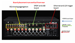
Before we remove the case, let us look at the back of the unit. It is like a layer cake. You can see a 3-layer sandwich of boards from those I/O positions. All those I/O jacks are attached to PC boards. The HDMI board is the first layer on top.
The second layer in the middle is composed of three boards, the analog RCA aggregation board at the right, the USB/ SPDIF board in the center, and finally the Ethernet/ 12V trigger board at the left.
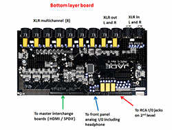
The third layer on the bottom is the PC board containing the data converters and analog components. This 3rd layer board has the XLR I/Os mounted at the back of the board.
Above is my PC board identification from a photo of the cover removed from the XMC-1.
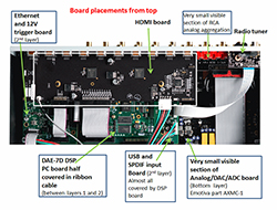
With the layering of the boards, only the HDMI board is completely visible.
The board with data converters and analog, at the bottom layer of unit, is almost impossible to see looking down from the top. We will see from a photo below that this it is the largest board in the XMC-1.
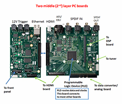
Above are photos of two boards at the second layer. Most of the chip numbers are not visible. I am not going to go into detail on these boards. This is not the place to discuss Ethernet controllers, and audio USB design needs its own article.
If Emotiva wanted to spend part of the bill of materials for parts to add features like multiple standards of wireless connectivity or Ethernet streaming audio functions, the added chips would go on these boards. Instead, Emotiva has chosen to put the money into the parts that affect the measured performance of the unit.
All boards have digital connectivity to a large Xilinx Programmable Logic Controller (PLC) on the USB/SPDIF board via ribbon cables. The PLC coordinates the digital audio data flow and associated clocks between all the boards. This part does not have to be located on this board, but placing it in the middle location on the second level reduces the cable lengths to the other boards.
The instruction book indicates the XMC-1 “does not support most multi-channel digital audio formats, including multi-channel PCM audio files or DSD” This may be a restriction imposed by the C-Media CS6631A USB 2.0 Audio Processor. Nothing in its data sheet indicates it can support these formats. If the CS6631A did produce multi-channel, the digital audio lines for the surrounds would have run from the USB audio chip to the PLD. It cannot be added in firmware.
A microcontroller and flash memory are also part of the system control and are likely on the front panel board for which I do not have a photo.
The large board at the bottom of the chassis contains the ADC, DAC, and analog components. This board, marked AXMC1, will be the subject of much of our discussion.
Note the open layout of components on the high quality PC board material. All PC boards are designed, manufactured and stuffed in the USA.
The audio DSP section is the DAE-7D, sold by Momentum Data System and found on much more expensive Pre/Pros sourced in the US and Canada.
http://mds.com/wp-content/uploads/Datasheets/Audio/DAE77_rev1d.pdf
Unlike other users of the DAE-7D, Emotiva makes its own copy of the board, stuffs it with parts, solders and tests it.
The DAE-7D DSP PC board is between layers 1 and 2 with no I/O connections to the back panel. It is half covered by the ribbon cable which brings the digital audio from the HDMI down to the DSP board. The HDMI board also covers the back of the DAE-7D DSP board.
The full DAE-7D board photo, printed in the MDS literature, is copyright and I cannot reproduce it here, but is at the above URL.
On the DAE-7D board are two TI dual 300MHz DA710 DSP chips designed for audio application (TI brands these Aureus). Between the two DSPs is an Asynchronous Sample Rate Converter (ASRC). The operation of this chip is discussed in the article linked below.
The photo of the DAE-7D PC board section shows a TI ASRC, but in the Momentum Data Systems literature, the chip is really fuzzy, and it’s hidden under other boards in the Emotiva. It appears to be a TI 4192 or TI 4193 which have identical performance specs. A smaller chance exists that it is a TI 4190 which has slightly reduced performance. These TI ASRCs are two channel parts, so four are used on the DAE-7D.
The first DSP chip on the DAE-7D board decodes Dolby and DTS signals coming from the HDMI video chips, including all the lossless formats. The DSP also processes the PCM inputs from HDMI, USB and SPDIF sources.
The second DSP performs functions such as delay, matrix decode (example DLP II), rudimentary bass management (2nd order high pass filters), parametric EQ, and other optional functions. The Parametric EQ can be replaced with filters downloaded from a room correction system. For the Emotiva, that is Dirac.
Computational space limitations in the second DSP limit the Dirac filter bank to a sampling rate 48K samples / sec. More expensive products with Dirac have additional DSPs which run at higher sampling rates.
Emotiva claims a close relationship with MDS and is moving ahead with a 16 channel implementation, at a much higher price point, that uses boards in the new MDS TI DA8xx Performance Audio Framework.
The new DAE 88A board, which supports Dolby ATMOS, has just been introduced by Momentum Data Systems.
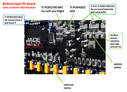
Below is the AXMC-1 Rev D PC board photo. The DAE-7D drives the DACs on the AXMC-1.
This is a complex circuit board that will be the focus of this article. The placements of the ADCs and DACs on the board are identified.
The board is filled with NE5532 op-amps and includes a few OPA2134 op-amps where a FET (Field Effect Transistor) input is required. FET inputs are required when the input bias current of the NE5532 can lead to large DC offsets. In AVRs and Pre/Pros priced below $3000, most op-amps are entry level with a few NE5532s sometimes showing up. Above this price point, higher priced op-amps or discrete op-amps, in the case of the Bryston SP3, replace the NE5532.
The main channel DACs are TI PCM 1796, which are found on many AVR and Pre/Pro products at or above $2,000. The PCM 1796 supports DSD, and the XSP-1 transfers DSD from HDMI to the DACs without DSP processing.
The performance of the PCM 1796 relative to other DACs is found in the chart below, along with products that use it. The chart will be updated with some 2015 products added soon.
www.hometheaterhifi.com/technical/technical-reviews/options-by-supplier-and-price/
Surrounding the DACs are opamps and surface mount resistors and capacitors, and their functions will be discussed in detail below. The physical separation of the DACs for the left and right channels from the DACs for the surrounds and subwoofers will become clear.
The ADC is the TI PCM4202. The worst case distortion is 17 bits equivalent. The worst case SNR is 18-bit equivalent. This is good enough not to degrade the performance of a good phono stage like the Emotiva XPS-1 in moving magnet mode; indeed it exceeds the requirements of the best measuring phono stages.
The circuitry surrounding the ADC performs the anti-alias filtering.
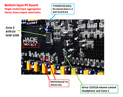
The PCM1502 DACs are associated with the stereo Zone 1, stereo Zone 2, and the record output jacks on the rear of the unit.
Note the complex circuitry surrounding the PCM 1796 DACs is internal to the PCM1502. As a result, the PCM1502’s distortion performance declines significantly. It is typical to find a reduced performance DAC for Zone and record functions relative to the main channel DACs in most AVR or Pre/Pro.
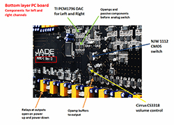
Above, I again show the AXMC-1 PC board photo, but this time I am only identifying chips involved in the signal flow from the PCM1796 DAC to XLR output jacks for the right and left channels. This prevents the photo from becoming too complex.
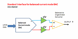
In the section on data converters, I noted the PCM 1796 DAC. This chip is balanced and has current outputs. Both techniques minimize distortion.
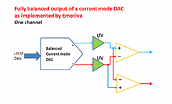
Above is a block diagram which shows how the balanced current output is converted to a single-ended voltage. Reactive components are used in this circuit blocks for the reconstruction filter.
The total noise on each side of the balanced circuit is the same as in a single-ended signal path. When the balanced anti-phase signals are finally converted to single-ended, the signal size will double. The noise is uncorrelated, so it goes up by only 3dB, yielding a 3dB SNR improvement.
The Emotiva XMC-1 has a fully balanced signal path from the DAC to the XLR outputs.
In the above figure, we see a modification Emotiva makes to the circuitry around the DAC. The object of the circuit is to produce a balanced output. You might expect that the balanced-to-single-ended converter could be eliminated, but instead we have two with the inputs to one reversed.
The reason the balanced-to-single-ended converters are retained is to take advantage of the reduced noise and distortion that occurs when the signal is converted to single-ended. It is better to do this intermediate step since the two balanced signals accumulate gain and phase errors with frequency as they pass through more circuitry, and the amount of distortion cancelled is reduced.
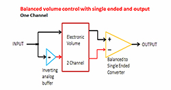
Balancing a volume control brings similar advantages to balancing the DAC with improved distortion and noise.
In the figure above, we see the standard method to use a stereo volume control and convert it to a balanced mono volume control. Note the analog inverter at the front of the volume control converts the incoming single-ended signal to balanced.
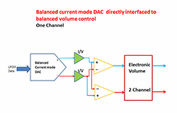
In the Emotiva, the analog invertor is eliminated. The DAC-stages balanced outputs are connected directly to volume controls. The Emotiva uses a Cirrus CS3318 8-channel control. Since the left and right channels require two channels, half the CS3318 is used. The remaining four volume segments are used for single-ended functions outlined below.
The CS3318 volume control is powered by +/-7.5VDC, a limit imposed by the CMOS process technology used for this part. This limits the signal swing at the input and output of the IC compared to the best electronic volume controls at +/-15VDC. The CS3318 also has internal op-amps which do not perform as well as the best external op-amps. By using the CS3318 in the balanced configuration, its performance more closely matches a single-ended volume control at +/-15VDC.
AVRs and Pre/Pros have many switches in the signal paths.
CMOS switches are the least expensive approach to switching analog signals, but they introduce distortion since the switch resistance changes with the signal level applied. Non-linear capacitance of a MOS device also adds distortion at higher frequencies.
To completely eliminate the distortion from the CMOS switches, relays must be substituted. This solution is adopted in the Bryston SP3. Bryston used 33 pairs of DPDT (Double Pole, Double Throw) relays in its very expensive Pre/Pro.
The XSP-1 Emotiva stereo preamp uses full relay switching, but that is a two-channel product, so the relay count is low.
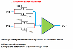
In the diagram above, a pair of CMOS switches is shown. The bottom switch is turned on, letting IN 2 pass to the output. The top pair is turned off blocking IN 1.
Emotiva uses the JRC (New Japan Radio) NJW1112 for the CMOS switch. The chip operates with +- 7.5VDC power rails which are a limitation imposed by the semiconductor process technology JRC uses for this device.
In the simple diagram above, I show only a two switch pair. The complete schematic of the NJW1112 shows complex switching array with 16 inputs and 8 outputs. The switch matrix has 72 NMOS-PMOS transistor pairs for maximum flexibility. With so many switches, the size of the transistors is small. As a result, the effective resistance of each switch, which varies with voltage, is high.
Only a small fraction of the switches are used in any given application.
www.njr.com/semicon/PDF/NJW1112_E.pdf
The New Japan Radio (JRC) NJW 1112 has an internal op-amp buffer past the CMOS switches. The op-amp in the NJW 1112 is not the best performing, since it is part of the switching chip, so it also runs at +/-7.5VDC.
The design restrictions on the op-amp are similar to the LSI AVR chip, but we need a buffer after the CMOS switch. Current must not flow in a CMOS switch lest we get distortion. The op-amp in the NJW1112 blocks the current flow to the digitally controlled volume control (Cirrus CS3318). The CS3318 has a minimum input resistance of 8k Ohms.
It is possible to get better distortion performance by replacing the NJW1112 with a solid-state switch that operates on a +/-15V supply rail and which have fewer, larger sized switches on the die. These +/-15V switches have no on board op-amp. The switch would be followed by an SSI op-amp buffer to prevent current flow in the switch.
I must note, however, that New Japan Radio has removed the +/-15V audio switch offerings with serial control pins from the website. These parts had no internal op-amps. Toshiba no longer makes these chips, which were very common even in lower priced products a few years ago. Rohm and Renasis also show no +/-15V audio switching chips on their websites now.
It is possible to purchase individual high voltage, low resistance switches, but they must be turned on individually with a separate digital chip converting the serial control stream from the CPU into the separate control wires. This complexity adds to cost and significantly increases PC board surface area. The problem is identical for relays, but with the additional issue that each relay must have a high current driver to energize the electromagnet which controls the relay.
I know New Japan Radio (JRC) has a +/-18V CMOS process which is used on its “high end” volume control with no op-amps (MUSES72320). That chip is used in the Emotiva XSP-1 stereo preamp. It is not clear why New Japan Radio does not offer switching chips with this process.
It is likely that unlisted +/-15V switching chips are available on an exclusive basis to companies running very high volume production, but such chips would not be available to Emotiva.
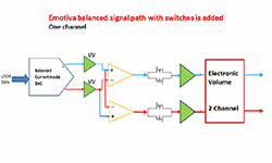
To reduce distortion, Emotiva again uses a balanced topology. The NJW1112 is placed in the balanced signal path between the DAC and the volume control. This is shown in the block diagram above.
Only the CMOS switch, in the closed position, connected to DAC, is shown in the block diagram. Open switches for analog direct path are not shown.
In theory, with the NJW1112 switch connected in balance, the performance should come close to a switch with a +/-15V power supply and SSI opamp. Some data sheets actually disclose performance improvement of a component in balance but not the NJW1112.
In practice, the gain offset between the channels will limit the cancelation of distortion. The circuit blocks in each single-ended path are not identical. They have slight amplitude and frequency response differences.
As we add more blocks in each single-ended path, the difference between the in phase and anti-phase paths increase and the ability to cancel distortion declines.
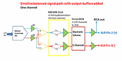
Above we see the full block diagram from DAC to XLR. Op-amps buffer the output of the volume control from the component connected to the XLR jacks. The balanced signal is passed directly to the power amplifier.
Not shown on the schematic is a relay at each output which is open on power up and power down to prevent transient signals that occur before the power supplies reach full voltage on power up or as the power supply collapses on power down. All relays for this function operate at the same time and need only one relay driver and one control wire. This is a significant cost saving that makes the relay more practical. This relay path is also the one with the highest signal amplitude and with an unknown load with the potential for significant current flow.
A traditional Pre/Pro has a single-ended signal path. The XLR output is produced using an inverter to produce the negative (pin 3) output. The power amp then converts this balanced signal back to single-ended. Little is accomplished here for small cable runs with good shielding. For the XMC-1, the signal is already balanced so a whole stage of electronics at the output is gone.
The Emotiva approach sounds nice at first, but it has just passed the job of performing the balanced-to-single-ended conversion to the power amp. As it leaves the XMC-1, the fully balanced signal contains the correlated even-order distortion. We also have yet to take the 3dB SNR improvement for the NJW1112 and CS3318 when we convert to single-ended.
For this reason, care needs to be taken in selecting the power amp to interface to the XMC-1.
In most power amps, the circuitry connected to the XLR inputs will not have good CMRR (common mode rejection ratio) to reject the even ordered harmonics, and the CMRR will decline with frequency.
The main stage of nearly all power amps is single-ended as shown above. The power amp designer spends little time designing the balanced-to single-ended converter at the front end of the power amp.
In the preamp, with an internal single-ended path, the signal is converted from single-ended to balanced before the XLR jack and then the power amp converts the balanced signal back to single-ended before it goes in to the main power amp electronics. The power amplifier designer may also see this circuit block as a place to cut costs. The designer understands the RCA output of the preamp and RCA inputs of the power amp cuts out electronics at both ends.
Dan Laufman, president of Emotiva, discusses the company’s design approach for the preamp:
“The main left and right channels are fully balanced, input to output. There is no single-ended-to-balanced conversion. This is why we label it a “Differential Reference” product. All of our “Differential Reference” products are fully balanced, not quasi balanced”.
I assume the Emotiva power amps are designed with the output of the company’s preamps in mind, but I do not have schematics of the products with a single-ended or bridged main amp topology to see what the differences are.
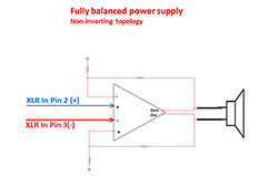
I did get a chance to look at the top of the line Emotiva power amp, XPA-1,which is fully balanced, making it ideal to interface with the XMC-1. Unfortunately, the SNR performance of the power amp was lower than expected, but a relatively simple change in the design can improve the SNR.
A block diagram of a fully balanced power amp, which does not have the noise problem, is shown above. This docks up to the Emotiva and will yield good performance.
If you have a power amp with only RCA inputs, the performance of the XMC-1 will decline.
The RCA outputs in the Emotiva XMC-1 come off pin 2 of the XLR. No balanced-to-single-ended converter is provided by Emotiva. As a result, the RCA outputs are in a single- ended signal path, with one section of the NJW1112 and one section of the CS3318. This is the same signal path that the surrounds and subwoofers have, as we will see in the next section. If the balanced-to-single-ended converter was included before the RCA output, the distortion would be reduced and the SNR increased.
Since Emotiva expects to dock the XMC-1 to one of the power amps they produce or a competitive power amp with excellent performance at the balanced XLR inputs, they see the added electronics to improve the RCA output of the XMC-1 as an added expense that is not required.
Each switch at the input of the volume control has four positions. Since the topology is balanced, the four signals at the switch inputs must also be balanced.
The first switch position is to connect the DAC to the volume control.
The second switch position is to connect the left and right RCA plugs of the 7.1 input to the volume control. The single-ended signal at the RCA plug is converted to balance by using an analog inverter before the negative polarity switch input.
The third position is for the stereo inputs (three on the rear panel and one on the front). Another set of selector switches with additional active electronics precede the connection to the NJW1112. This will be discussed below. Since the stereo inputs are single-ended, they are also converted to balance with an analog inverter to drive the negative polarity switch.
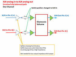
The most interesting switch position is the fourth when the XLR analog input is passed directly to the balanced switches. I show this signal flow below:
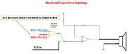
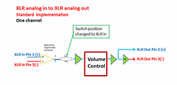
In a traditional preamp design (stereo or multi-channel), the balanced XLR input is converted to single-ended and then follows through the single-ended path of the component. This signal flow is shown below:
In the XMC-1, electronics associated with converting the XLR input to single ended are eliminated along with the noise and distortion they introduce.
As emphasized above, you need a power amplifier with excellent electronics in the stage which converts the balanced signal back to single ended or a fully balanced power amplifier to get the performance enhancement.
The key take away is the XLR input will have significantly better noise and distortion performance than the four single ended inputs. Those inputs are first aggregated with another set of switches, then buffered and converted to balanced, before entering the NJW1112 switch.
It should come as no surprise that Robert Kozel’s measurements show the XLR input to have significantly lower distortion than the RCA input.
As an aside, the XLR inputs are directly switched to the ADC which has balanced inputs (most quality audio ADCs have balanced inputs). In a standard Pre/Pro or AVR, the added electronics of a single-ended-to-balanced converter is needed before the ADC.
Given the quality of the ADC, you want a phono preamp with XLR outputs plugged into the XMC-1. The alternative use is to listen to phono with room correction. Strangely, Emotiva does not have a phono preamp with balanced outputs.
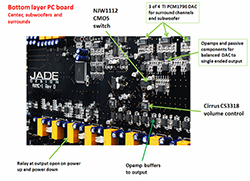
Above, I again show the XMC-1 PC board photo, but this time I am only identifying chips involved in the signal flow from the PCM1796 DAC to XLR output jacks for the center, surround and subwoofer channels.
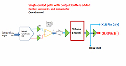
The block diagram above shows the signal flow from the DAC to XLR outputs for the center, surrounds and subwoofer channels.
Since the PCM1796 is used for all channels, and this DAC is a fully balanced current mode device, the circuitry around it that we discussed above is retained.
The switch and volume control are single-ended. Note we need an extra inverter to convert the single-ended signal path to balance for the XLR output. This is the same signal flow for other Pre/Pros with XLR outputs. On the positive, the single-ended Cirrus CS3318 volume control on all channels is a step up from the AVR LSI, and all op-amps in the signal path are the NE5532.
I also note the performance requirements on the subwoofer path are reduced, and a single-ended path is adequate.
The switch has only two positions: the DAC output or the 7.1 multi-channel RCA inputs. I question the usefulness of these inputs for a product with a high quality internal DAC. NAD has jettisoned the 7.1 inputs on its highest priced products which have no AVR LSI. With the 7.1 inputs gone, we have no switch in the signal path for the center, surround or subwoofer. If the product has an AVR LSI, the switch is internal and cannot be bypassed. Of interest is an examination of the complete XMC-1 final design (below), which showed an unused volume control and some unused switch segments. It would have been possible to balance the center channel, but it is easier to see this back seat designing after the entire system has been engineered, then predicting it was possible during the design.
All two-channel single-ended inputs (3 back and 1 front) and the tuner signal are connected to a New Japanese Radio (JRC) NJW1298 AVR LSI.
www.njr.com/semicon/PDF/NJW1298_E.pdf
It is common to use AVR LSI chips for analog stereo Zone functions and tape outputs. Indeed this was the prime use of AVR LSIs outside budget AVRs before the cost reductions on the main channel began.
This part not only aggregates these inputs but also allows independent switching for the main zone, two additional stereo zones and the tape monitor.
The main channel left and right outputs from the NJW 1298 are converted to balanced signals internally in the NJW1298 and enter the balanced volume control through the NJW1112 switch which was discussed above. The balanced main channel can pass direct to the volume control or the ADC. Since the XMC-1 uses the excellent TI PCM4202 ADC, the room correction functions and multichannel surround synthesis function are used with out sonic degradation.
Almost all ADCs, even in entry level AVRs, have balanced inputs. It is for this reason the NJW 1298 has balanced main channel outputs.
The XMC-1 makes all inputs, analog or digital, available to all zones. Not all products do this because of the added parts complexity.
Stereo Zone 1, Zone 2 and the Record Out require HDMI mixed to stereo in the digital domain (before any room correction or other processing). The HDMI digital stereo signals are converted to analog by the TI PCM5102 DAC single-ended voltage mode. While this DACs performance is a significant reduction over the TI PCM1796 used for the main channels, it should be good enough for systems connected to the external zones. Similar quality DACs are seen in most AVRs or Pre/Pros for external Zones.
Stereo Zone 1, Zone 2, and Record need a converted source for DSD in stereo. The TI PCM5102 will not accept DSD inputs, so the stereo signal is created by the summation of the 5.1 signal coming from the output of the main PCM1796 DACs. Even if the TI PCM5102 had a DSD input, it would not have been used. Summation of the 5.1 DSD signal cannot be done in the digital domain since the resultant signal is no longer a 1 bit stream.
Most AVRs and Pre/Pros I have examined that support DSD do not have this added electronics, but require you to select the DSD two-channel layer of an SACD at the source component. The XMC-1 USB input does not pass multi-channel DSD. If it did this, an analog summation circuit would be mandatory since only the multi-channel DSD file was purchased.
You may ask why not also perform an analog summation of the PCM1796 DAC and eliminate the TI PCM5102 for HDMI decode? The answer is the main channels may have room correction applied. They also have been delayed to align the speakers, and this would cause phase cancelation. DSD does not pass through the DSP, so it gets no processing and is suitable for analog summation.
The 7.1 RCA inputs are also summed in the analog domain to stereo by a pair of op-amps. The XLR input is converted to single-ended.
Zone 1 exits the NJW1298 and passes through a pair of sections of the CS3318 volume control before terminating at the RCA output plugs. The Zone 1 volume tracks the main volume and cannot be adjusted independently. I do not understand why Zone 1 does not have independent volume since it is being reproduced in another room.
With two CS3318 chips, we have 16 total sections, and 11 are used for the multi-channel main outputs. The 11 sections for the main outputs include 4 for the balanced left and right channels, 2 for the single-ended subwoofers channels, and 5 for the single-ended center and surrounds channels.
The headphone volume control uses an additional pair of CS3318 sections which can be set independently. The total count is 15 sections with 16 available. The one unused CS3318 section could have been used as part of the signal path for a balanced center.
The input to the headphone control is from the PCM1796 DACs. When the headphone is plugged in, the DSP mixes to stereo, and all internal EQ processing is disabled.
The other TI PCM5102 is for Zone 2. Zone 2 can be configured to play audio from a different source (either digital or analog). For the S/PDIF and AES/EBU signals, an independent digital switcher is used, which routes the selected signal to the Zone 2 PCM5102. The electronic volume for Zone 2 is on the NJW1298.
In total, 10 analog independent stereo inputs are selected by the NJW1298 for Zone 2. There are two from the PCM5102 DACs (HDMI and SPDIF), the four stereo analog inputs, tuner, the XLR input converted to single-ended, DSD mixed, and 7.1 RCA mixed.
Although it could be independent, Emotiva sends the signal on Zone 1 to tape out.
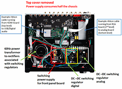
Note the power supplies take up half the area of the unit. Three switching regulators are identified. The first switcher is for the front panel, a second for digital boards, and a third for the AXMC-1 analog board.
The first switcher is powered directly by the AC line. This regulated output keeps the front panel alive, waiting for front panel or remote command for the system to power up.
The remaining two switching power supplies work off of lower voltages coming from the toroid transformer. The transformer outputs are rectified and the switchers operate as DC-to-DC converters.
A switching power supply is used for the digital circuits to improve efficiency. With all the added functionality of a modern Pre/Pro, the digital current demands are going up. You can see the large number of VLSI circuits on the boards in the top and middle layer.
The analog switching power supply board generates +5VDC only.
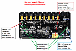
On the analog board, more switching regulators are present and identified in the XMC1 photo above. These are Linear Technology LT8582 dual boost / inverting DC to DC Converters. One chip is used to produce +/-7.5VDC from the incoming 5VDC and the other +/-15VDC. The switching frequency is approximately 2MHz.
The +/-7.5V supply is for all analog electronics except for the op-amps connected to the XLR and RCA outputs. Those operate on the +/-15V rail.
While the internal op-amps could be run off +/-15V rails, Emotiva choose to insure maximum reliability by keeping the op-amps at the same supply voltage as the New Japan Radio NJW1112, NJW1298 and the Cirrus CS3318. It is possible, especially on power up or down for the op-amp to produce an output transient near its power supply. This could damage the parts on the lower power supply.
One solution is to place a small protection resistor between the op-amp and ICs at the lower power supply voltages, but this has the potential to create more distortion than the lower supply rail on the opamp. At least one product I have evaluated does nothing, assuming the op-amp current limit will keep the switch IC from being damaged.
Switching regulators are rare for analog and data converters supply rails. In addition to reducing losses as heat, the switching regulators line hum is significantly reduced. The trade is that the high frequency switching clock must be kept off the analog supply rail.
The data converters operate on lower supplies 5VDC and 3.3VDC, which are the maximum voltages that can be applied to fine-line CMOS technology used for the ADCs and DACs. These supplies are from linear regulators, which help to reduce switching regulator noise.
Taking our final look at the XMC1 board, we see three more relays for a total of twelve. These extra relays perform the same function as the nine we identified above. They prevent transients that occur on power up and power down from appearing at the outputs of the main channels, stereo Zone 1 out, stereo Zone 2 out, and record out.
All twelve relays are connected to one power drive that energizes the electromagnets. This power driver needs only one control line. We have twelve relays here so why not more? As explained above, substituting all the independent electronic switches with relays gets more expensive, since each needs its own power driver, and each power driver must be addressed by its own individual digital control signal. In the end, we have could have more than 10 – 20 drivers on the board dependent on if the zone 2 is relay switched.
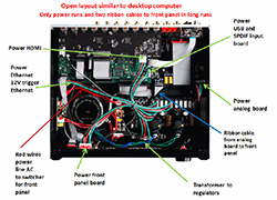
The connection between the power supply and the PC boards is shown in the photo. This again allows us to identify the boards, and note the clean and open layout of the unit. I have called out each connection in the power wiring harness.
I have identified a couple of ribbon cables which interconnect the PC boards in this figure and the one proceeding it. Except for the long runs to the front panel, all are kept short at the back of the unit.
The long ribbon from the analog board to the front panel is for the headphone jack and front panel stereo input. To prevent hum or noise, the analog signals running on the ribbon cable are balanced. This is surprisingly heroic for the front panel mini-phone plug input designed to interface with smart phones. To do this, four op-amp sections and associated passives are on the front panel to convert the stereo signal to balanced and on the other side of the ribbon cable on the XMC1 for more op-amp sections to bring it back to single-ended so it connects the front end switch of the NJW1298.
The TI headphone driver IC (TI TPA6130) is on the front panel, and this part has balanced inputs, so extra op-amps only need to be added. With headphones, it is clear why Emotiva engineers run the cable ribbon cable balanced. With closed back headphones the smallest amount of hum or noise will be audible.
The Texas Instrument step up headphone driver IC is the TI TPA6120 which can produce much more power than the TPA6130, but it needs a +/-15V supply. Putting a +/-15V supply on the front panel would require another switching boost inverter DC – DC converter, adding even more to the bill of materials for the headphone signal path. Emotiva must have judged costumers with expensive headphones are likely to use an external headphone amp. Emotiva can supply application information for optimal connection information for a headphone amp, so it is driven by the PCM 1796 DACs. The instruction manual suggests using stereo zone 1, but this is not the optimal solution.
At the beginning of this piece I said the XMC-1 is a paradigm of a Pro/Pro implementation. What could be done to improve it?
Some designers would want to increase the complexity of the analog power supply regulators, but it is not clear to me this is required. The tradeoffs between using switched or linear regulation in the analog power supply is an area of significant debate between design teams
Outside the power regulators, most changes would be part substitutions of the DACs, op-amps and volume controls. The part options are discussed throughout Parts I-III of my AVR build quality series. All channels could be balanced, and finally the CMOS switches would be replaced by relays.
The price increase would be significant for this multi-channel system. For stereo preamps, the upgrades can be made without a dramatic price increase. The Emotiva XSP-1 is an example.
Aside from using it as a model for this article, the bottom line on the Emotiva XMC-1 is that it is a great processor for the price, and it has some unique design features.
I would like to thank Robert Kozel for reviewing this article.


