

Using KT88 pentode output tubes, it is specified at 70 Watts output per channel into 4 Ohms, and with KT120 pentode output tubes, 110 Watts per channel into 4 Ohms. The sound is warm and sweet, like a good latté with half a teaspoon of dark chocolate (I guess that would actually be a mocha latté, even better). No harshness, no grit. Just plush, lush audio enjoyment.
Octave Audio V 110 SE Integrated Tube Amplifier Highlights
- Built like a tank.
- User-adjustable bias.
- Interchangeable tubes KT88 or KT120.
- Adjustable damping factor by changing the input tube.
- Sings like a lark.
- Shines in the dark.
Octave Audio is a German high-end audio company. Their product line spans preamplifiers, power amplifiers, and integrated amplifiers. The V 110 SE, reviewed here, is an integrated amplifier.

The basic model, at $9,500 USD, comes with four KT88 pentode power tubes which have a 70 Watts per channel into 4 Ohms rating. If you prefer more power, you can order the amplifier with four KT120 pentodes delivering 110 Watts per channel. KT150s used to be an additional option, but this is no longer available.
Type:
All tube signal path
Solid-state power supply
Rated Power:
70 Watts per Channel with KT88 tubes into 4 Ohms
110 Watts per Channel with KT120 tubes into 4 Ohms
Frequency Response:
20 Hz – 70 kHz, +0 – 3dB, 90 Watts
THD + N:
0.1%, 10 Watts, 4 Ohms
Signal-to-Noise Ratio:
-100 dB, 90 Watts
Output Impedance:
2 Ohms
Eco Mode:
Turns power down after 15 minutes of no music signal
Bias:
User adjustable
Soft Start Protection:
Yes
Adjustable Damping Factor:
Choice of three different input tubes for adjusting the damping factor (they all come with the amplifier)
Remote Control:
Yes (volume)
Choice of Color:
Silver or black
Dimensions:
17.8″ (451 mm) W x 6.9″ (175 mm) H x 16.3″ (415 mm) D
Weight:
49.2 Pounds, 22.3 kg
MSRP:
$9,500 USD, fit with KT-88 S4A Carbon output tubes, line version
Add $850 for MC or MM phono stage
Add $800 for optional KT120 output tubes (instead of KT-88 S4A)
Options can be acquired/added later through Authorized Dealers
Website:
SECRETS Tags:
Octave Audio, V 110, SE, Integrated, Tube, Amplifier, Preamplifiers
Secrets Sponsor
The Octave Audio V 110 SE is the second edition of the V 110.
It uses a choice of KT88 or KT120 power tubes. Each model dissipates about half of its model number in watts at the plates. So, a pair of each tube can output about 70 watts and 110 Watts, respectively. The KT88 and KT120 are beam pentodes. The KT150, which used to be another option, is a beam tetrode. The “pin-out” diagrams of the KT88, KT120, and KT150 are shown below. Pins 2 and 7 are connected to voltage that makes it hot, and that makes the cathode, connected to pin 8, hot. as well. The hot cathode forms a cloud of electrons which are negatively charged and attracted to the positively charged plate, pin 3. The musical signal is applied to the control grid, pin 5, which affects the flow of electrons. The screen grid, pin 4, and the suppressor grid, pin 8, make the flow of electrons between the cathode and plate more efficient. This is discussed again for clarification, a few paragraphs below, in relation to control grid bias.

Although the signal path is pure tube, the power supply for the V 110 SE is designed around solid-state rectification devices because they are superior to tube diodes (rectifiers) in the following ways: Solid-state rectifiers have less voltage drop (sag) and deliver current more quickly. They also do not change with age and have less series resistance.
The amount of power supply capacitance in µF (micro-Farads) for a tube amplifier does not have to be as high as it is for a solid-state amplifier because the voltages used in tube amplifiers are much higher, e.g., 600 Volts for tubes compared to 40 Volts for solid-state.
The relationship between capacitance and voltage is a square ratio. So, if in a tube amplifier, the capacitance in the power supply is 500 µF at 600 Volts, the capacitance in a solid-state amplifier power supply with a voltage rail of 40 Volts would be about 110,000 µF.
Each of the two types of power tubes requires a different bias voltage (current) on the grid which makes the tube’s grid send a specific amount of current to the plate whether music is playing or not. This is called Class A bias. If it is not being directed to the speakers, that bias current is dissipated as heat at the plate. It’s obviously inefficient, but Class A biased sound is the best sound because the signal within that current is instantly sent to the speakers.
The V 110 SE has individual bias voltage adjustments for the output tubes on the front of the amplifier by inserting a small screwdriver (included) into four small holes. All Octave amplifiers come from the factory with bias levels preset for the stock tubes, and normally one should not have to worry about checking or changing the bias level for 2-3 years; however, changing tubes will require the bias voltage to be adjusted using a straightforward system Octave developed for all their amplifiers. For those of you who love tweaking your system, you can check the bias settings and adjust them anytime you want.
The bias adjustment changes the amount of negative voltage charge (in relation to the cathode) on the grid. There is always some amount of negative charge on the grid, and it is not desirable to ever have it go positive (the amplifier would go into runaway and burn up). The amount of negative charge determines how much current flows between the cathode and the plate, as a negative voltage charge on the grid repels the negatively charged electrons in the cloud surrounding the heated, glowing cathode.
In a pentode tube, there are five elements: The cathode, anode (plate), control grid, screen grid, and suppressor grid. The screen grid is an electrostatic shield between the control grid and the plate and works by lowering the capacitance between the cathode and the plate. The suppressor grid, which is between the screen grid and the plate, directs secondary emission electrons that escape from the plate back to the plate by being negatively charged, which pushes the negatively charged electrons away. It is usually wired attached to the cathode. The result of the addition of the screen grid and suppressor grid increases the efficiency and power output far beyond what a triode tube can produce.
When there is no music playing, the bias will cause a certain amount of current to flow between the cathode and the anode (plate). This is the amount of Class A bias, which is what I adjusted in the V 110 SE. When music is playing, the preamplifier sends a small amount of voltage to the grid, and as it goes positive and negative with the waveform, it goes more and less negative in time with the music, causing pulses of electrons to flow from the cathode to the plate, and the output at the plate goes to the speakers as much higher voltage . . . . and we have, voilá, amplification. The V 110 SE, biased properly, delivers from 3 to 8 Watts in Class A. That is enough for low-volume level listening.
Andreas Hofmann, chief design engineer at Octave Audio discusses bias:
“Indeed a tube needs a negative voltage of the Grid 1 to set a defined Quiescent (bias) current. To do this we have the regulators and the BIAS Led display on board of the unit. The level of this current depends on the design of the power amplifier. In our Push Pull A/B Design, this current is around 15-20% of the maximum current the tube can deliver. The quiescent current is usually set to this fixed value ( 15 – 20% ) using regulators. This is why this variant is also called FIXED bias or fixed negative voltage.
For our Class A power amplifiers (Jubilee 300B, V 70 Class A, V16), the idle current is 50% of the maximum current. This current can also be adjusted using a regulator, but we employ an automatic self-adjustment circuit using a special tube circuit in our Class A power amplifiers. This variant is therefore called cathode BIAS or automatic grid voltage generation. This variant has the advantage that the tube adjusts itself as it ages. The general disadvantage is the high current load without a music signal, which limits the maximum output power of the power amplifier (not to be confused with an electronic quiescent current control using a processor, such controls always have the problem of calculating a music signal from the quiescent current, which is very difficult or impossible to achieve). The current from the output tubes, modulated with the music signal during playback, ALWAYS flows through the output transformer. This then only transmits the current that changes, i.e. the music component. This is a simple explanation of the BIAS setting for the two power amplifier types, Class AB and Class A. A discussion of the sound differences between A and AB operation is a different issue that will not be discussed further here.”
Here is a schematic of the bias circuit for a pentode output tube.
![]()
Photos below show the bias adjustment for the four KT88 tubes that were included when the amp arrived here. The first one shows the yellow LEDs which indicate the bias has not been adjusted yet, and that was because the KT120’s, for which the bias had been adjusted, had not been shipped to me yet. The second photo has three of the tubes’ bias adjusted so that green and red LEDs are illuminated. The included screwdriver is inserted into the fourth bias adjustment hole to be adjusted. The third photo is after the fourth tube bias was adjusted. Click on the third photo to see a large version that will also let you see the labels on each of the dials.


Even after the bias is adjusted, it takes the amplifier about 10-15 minutes to warm up when first turned on such that the bias LEDs are in their proper state. The bias can be viewed by turning the input selector dial on the left to the sixth position (it is unmarked; go to one position past “CD-2). I also noticed that after listening to music for a few days, I had to re-adjust the bias as the tubes were broken in. Again, however, the bias had been adjusted at the factory for the KT120’s which were still in shipment to me.
Here is a photo of the adjusted bias menu after only a few minutes of warmup, cage mounted (see second photo below), and several messy fingerprints (this was about a week after being in use, and we listened all day, every day). Two of the tubes are not warmed up. You can easily see if it is fully warmed up by just switching to the bias menu. Once the bias is correctly set, it will warm up to the proper levels after turning on the amplifier.

There is a slotted sheet metal cage that covers the tubes. It is recommended to have that cage on rather than off, presumably to prevent getting accidentally burned.

The mounted tube arrangement is shown in the photo below. The four KT88’s are in the rear. From right to left in the front are the input tube, the phase splitter tube for one channel, and the phase splitter tube for the other channel. The phase is split so that the positive portion of the waveform (00 to 1800) in each channel goes to one of the output tubes in that channel, and the negative portion of the waveform (1800 to 3600) goes to the other power tube in that channel. For the three triodes in the V 110 SE, all are dual triodes, with the left channel on one triode and the right channel on the other triode of the input tube, and the + and – phases for each channel in the 2nd and 3rd tubes. (There will be a test on this later, so study hard.)

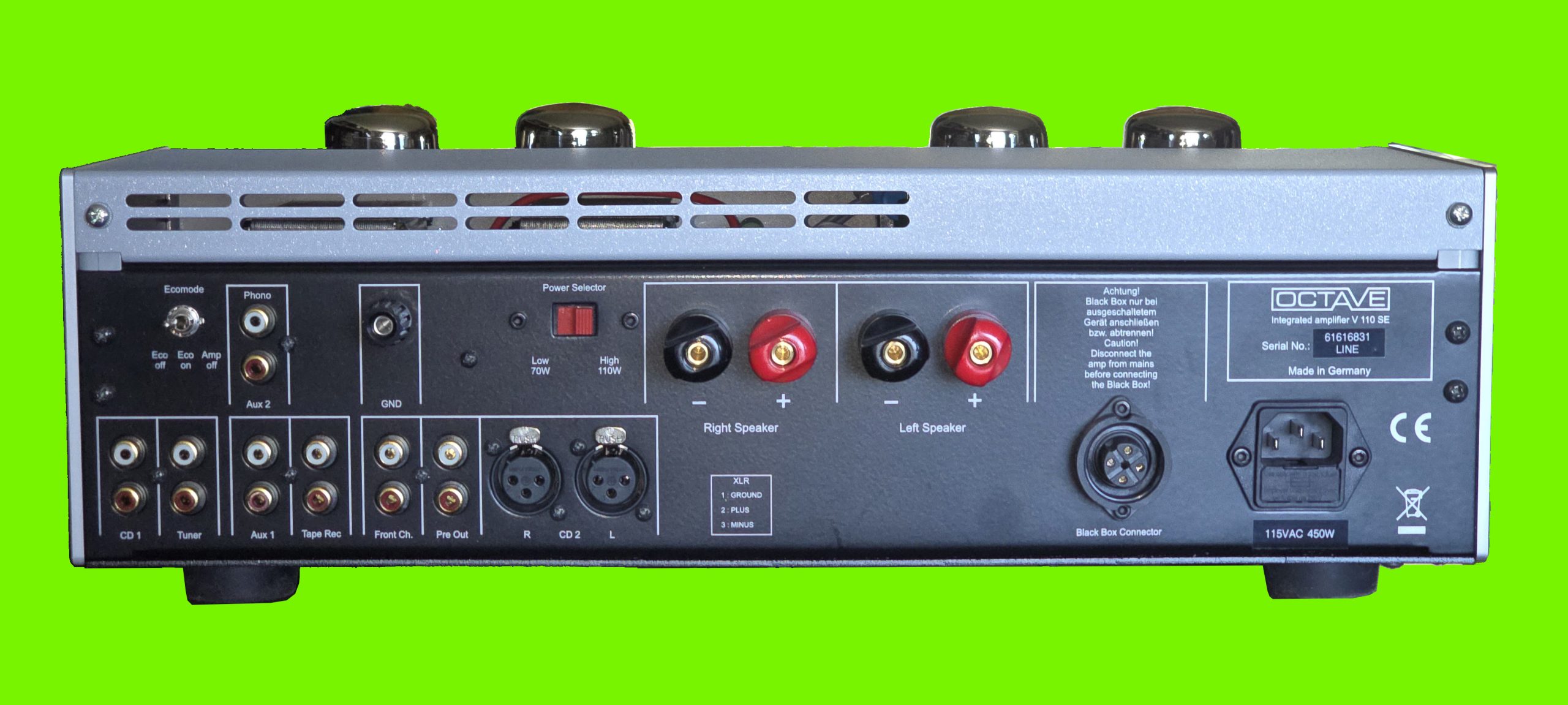
The rear panel has six RCA unbalanced inputs and one set of XLR inputs (bottom left). There is a toggle for the “Eco Mode” which powers down the V 110 SE to 10 Watts if there is no signal for several minutes. If you have the phono option, there is a set of RCA phono inputs as well. A ground terminal is to the right of the phono inputs. A red switch is next, and this is used to set the maximum voltage for the KT88’s (or equivalent) – Low Power, and KT120’s (or equivalent) – High Power. Note that the KT88 S4A Carbon tubes that come with the amplifier can be used in the High Power setting.
Next are the banana jacks for the right and left channels respectively. After that is a jack for the optional Black Box and Super Black Box which contain additional power supply capacitance. Then comes the grounded 120 Volt AC socket. The power on/off toggle is on the side of the front left of the amplifier.
A nice remote control is included that adjusts the volume. It is solid metal and heavy for a remote.

Here is a schematic diagram of a single-channel power amplifier with a triode phase splitter (6SL7) and two pentode output tubes (6V6). Notice that the capacitors in the power supply (at the bottom of the schematic) are only 47 µF, but they are 450 Volts. The 2nd and 3rd triodes from the right on the V 110 SE are the phase splitters for the two channels in the V 110 SE. Instead of 6V6’s, the V 110 SE has KT88s or KT120s.
 & two pentode output tubes (6V6) Schematic Diagram View")
© https://diyaudioprojects.com/Schematics/DIY-Push-Pull-PP-6V6-Tube-Amplifier/
You can change the input tube (the small tube on the far right in the photo) depending on the damping factor that you want. The factory-installed tube (12AT7 or ECC81) is for medium damping factor, such as for conventional cone speakers. The high damping factor tube (12AX7 or ECC83) is for difficult loads, like electrostatic speakers, and the low damping factor tube (12AU7 or ECC82) is for easy loads, like horn speakers. Each of the three included input tubes is marked high, medium, and low. I ultimately decided on the high damping factor tube, the 12AX7, as the 12AT7 resulted in too much bass with my Sonus faber Lilium speakers. For the bench tests, however, I used the factory-installed 12AT7.
The damping factor refers to the ability to keep the bass driver under full control. The plates of tubes themselves have a high output impedance, in the thousands of Ohms, which will result in a far too low damping factor. So, to remedy this problem, tube amplifiers usually have output transformers that lower the output impedance. They also eliminate the high voltage on the plate from being directly connected to the speaker.
Here is Andreas Hoffman’s explanation of how the choice of input tubes affects the damping factor:
“Indeed the switchable input tube affects the feedback because of the differences in the gain of the particular tube. This results in different open loop gain settings – and with the constant feedback network we use, this results in differences in the Output resistance. That said, it should come as no surprise there is lower distortion when the high damping factor/feedback tube is used. In any event, the feature is provided so V 110 SE owners have a better possibility to match the amp with their speaker to their taste.”
The reason a low output impedance is important is that, with the input impedance of a speaker being about 4-8 Ohms, the amplifier’s output impedance forms a voltage divider such that there is a voltage drop across the speakers. The ideal output impedance would be zero Ohms. Since this is not possible, what we would hope for is 1/100th output impedance compared to the input impedance of the device connected to the output. This is easy when connecting the output of a preamplifier to the 10 kOhms – 100 kOhms input impedance of a power amplifier. But for a power amplifier connected to a pair of speakers with 4-8 Ohms impedance, this is much more difficult. The output impedance of a solid-state power amplifier is usually less than 1 Ohm, but for a tube power amplifier, it is usually between 1 and 5 Ohms even with the output transformer. So, at least a small amount of voltage drop is inevitable with the tube amplifier. The V 110 SE has an output impedance of 2 Ohms.
The input circuit from the volume control to the input tube was a solid-state op-amp in the V 110. Op-amps have excellent gain, high input impedance, low output impedance, and low distortion. In the V 110 SE, the voltage from the volume control goes directly to the input tube which provides voltage gain. The phase-splitter tubes produce a small amount of current gain which drives the output tubes to full current. So, there are three gain stages here.
Andreas Hofmann discusses the difference in the input circuit between the V 110 and the V 110 SE:
“Indeed the first series V 110 had a different input gain stage. The V 110 design used an OP amp in the input, and then tube gain stages after. This is still the design of the V 40 SE and the V 70 SE. The V 110 SE and the V 80SE are “ all tube “ designs. By optimizing the first input tube circuit I removed the OP from the signal path. The reason is not the damping factor. The reason is the Open Loop gain on the one side, and the circuit stability of the first stage – the tube that is also handling the feedback – on the other. If you drive a tube directly with the volume regulator, which is a high-impedance source, this can result in an unstable phase response, finally affecting a change in the frequency response. This affects the stability of the feedback. But as mentioned before, the optimized input circuitry of the input tube 12 AX 7 circuit prevents this effect and improves the sound.”
The V 110 SE does not employ much negative feedback (a small amount of current from the + side of the output feeding back to the – side of the input through a resistor). The chief designer at Octave Audio, Andreas Hofmann, wants to have the amplifier very stable. There are a lot of advantages of negative feedback though. These include lowering the output impedance, reducing distortion, and increasing the bandwidth (frequency response). The downside is that it can make the amplifier unstable by producing oscillation (output going to input back to output back to input over and over).
I listened to the Octave Audio V 110 SE using Qobuz streaming from the USB-A output on a laptop to the USB-B input on an AURALiC ALTAIR G1 Digital Audio Streamer with its XLR analog outputs connected to the XLR input set on the V110SE. The speakers were Sonus faber Lilium.
Tchaikovsky’s 1812 Overture is one of the most famous classical music pieces ever composed. This version was released in 2001 by Telarc. Instead of the orchestra playing all of the parts, a choir was included here. What I wanted to see was if the V110SE could handle the cannons. It did, even with just the relatively low-output KT88’s in place. However, when the music swelled, and the orchestra as well as the choir were going full-blast, with the volume control at a middle level, I could hear congestion.
The reason for this is straightforward. If we look at a single sine wave test signal, say 1 kHz, on a spectrum analyzer at, say, 20 Volts output into 8 Ohms (50 Watts) using a 100 Watt amplifier, it shows the test signal and its harmonics. Well, music is not just a single sine wave. It consists of many simultaneous sine waves. Depending on the music, it could be hundreds of sine waves, which was the case in this album when both the orchestra and choir were going full-steam, The result is that, although the peak of the spectrum might be 20 Volts, the Total Power will be much more than that, and if it exceeds the amplifier’s capability, the sound will be congested due to a lot of harmonic distortion. In the case of the V 110 SE with KT88’s, this occurred. It did not sound harsh because tubes distort in a smoother manner than transistors. But, it was congested. So, if you like to play your music loud, I would suggest getting the V110SE with KT120 tubes.
To illustrate, here is an example of a 1 Volt, 1 kHz sine wave using my sound card with its outputs connected to its inputs (no amplifier in the circuit). The amplitude is 1 Volt, and the total power is 1 Volt.

Now let’s take a look at multiple sine waves with as close to 1 Volt amplitude as I could get with my sound card. It would not let me go into clipping, so it was limited to 0.78 Volts amplitude. The total power is 2.47 Volts, which is 5.15 times as much as the amplitude voltage, and you can see some harmonics starting to pile up, especially above 4 kHz. So, imagine the amplifier trying to deliver full voltage with a complex musical waveform that has hundreds of sine waves. Result? Major clipping.
The bottom line of this is that you can never have too much power, only not enough power. But, it depends on your listening habits and the type of music you listen to. For a system where you play music mostly as background to dinner or having your friends over for drinks, you don’t need a 1,200 Watt power amplifier. For me, I would use this amplifier for easy listening in my living room. It would work perfectly.


Erich Kunzel/Cincinnati Pops Orchestra, “Tchaikovsky: 1812 Overture & Other Orchestral Works”
The congestion that I heard in the 1812 Overture with the KT88’s at higher volume was not harsh. That is one of the beautiful things about tubes. They clip softly. A solid state amplifier with clipping like this would sound harsh. It is clipping either way though, and it is not desirable. Using more powerful tubes like the KT120 is one way to reduce its occurrence. When I changed to the KT120’s, that congestion at higher volume was audibly reduced. On the other hand, I felt that the KT88’s delivered a bit more “warmth” in the midrange at modest listening levels. The choice all depends on what you want and how loud you like it to be.

Anne Akiko Meyers, “The Four Seasons: The Vivaldi Album”
Vivaldi’s The Four Seasons is another classical favorite. Anne Akiko Meyers is the solo violinist on this album released in 2014. The V 110 SE exhibited its warm, smooth tube characteristics beautifully. Despite intense playing on her strings, there was no strident edginess. It had the transients that are natural to the instrument, but no objectional additions. I was not familiar with this musician, and I just happened onto the album. She is really something else! This is the best rendition I have ever heard.

Anne Akiko Meyers, “Mirror in Mirror”
Here is another beautiful album, Mirror in Mirror, by Anne Akiko Meyers. It is a showcase for her brilliant musicianship. The piano is just a backdrop for her. There was not a hint of over-sibilance. I was drowning in lush, sugary, eye-watering notes. Track 2, “Fratres”, was beyond description. I could hear the rosin on the strings. Just the right amount of edge transients. Just the right amount of everything. The difference between the KT88’s and KT120’s is simply one of more power, about 30 Watts more (KT120’s). At moderate volume, they sound the same. Fabulous! I elect for the KT120’s.

The London Oratory Schola Cantorum/Charles Cole, “Sacred Treasures of Venice”
Speaking of choirs, this new album, released in February, 2024, contains some really extraordinary music. It’s called Sacred Treasures of Venice and contains motets from the golden age of Venetian polyphony. First of all, a motet is a piece composed for choir with no orchestral accompaniment. This is different than a choir singing musical pieces like Christmas songs. Polyphony refers to the various voices in the choir singing at different melodies and rhythms. If everyone is singing the same melody and rhythm, then it is called homophony. Anyway, the individual voices on this album sounded glorious with the V 110 SE. Tube amplifiers shine with such music. Sopranos in particular, just soared.

Louis Lane/Atlanta Symphony Orchestra, “Copland: Appalachian Spring Rodeo Fanfare for the Common Man”
You have seen this cover art several times before in my reviews. It is a favorite (obviously). It was released in 1982 just as digital recording technology was in its infancy. The result is that it is not recorded very well and has some tinniness. That is one of the reasons I use it, to see if the DUT (Device Under Test) can soften that harshness. The V 110 SE did just that. And, it handled the deep pounding thuds of the bass drum, even though the KT88’s were in place. So, this amplifier can deal with demanding transients. When I beefed the amplifier up with the KT120’s, I could turn the volume up enough that it made a positive difference in the presentation, which is supposed to be loud.

Sonny Rollins Qartet, “Tenor Madness”
Sonny Rollins was a classic jazz tenor sax player at about the same time as John Coltrane. This album, Tenor Madness, was originally released in 1956 and re-released here in 2015. Because the original was on tape, and by 2015, digital remastering had reached a very high level, the sound of this nearly 70 year-old recording is something else (meaning really, really good). The title track has both Rollins and Coltrane playing, which is the only recording that had them paired together. Their saxophones sounded about as close to live in my listening room as I can imagine.

Charles Mingus, “Changes: The Complete 1970s Atlantic Studio Recordings”
Charles Mingus was a jazz double bassist. This album contains some of his music from seven albums recorded between 1973 and 1978 (he passed in 1979). The V 110 SE did those deep bass strings full justice, but what I was particularly interested in is in the opening track where some high frequency bells are rung. They had just the right amount of overtones to them, not gritty, not flat.

Black Art Jazz Collective, “Truth to Power”
Today, February 24, 2024, the following album, Black Art Jazz Collective – Truth to Power, was released. This is one of the most appealing aspects of streaming high-res music, in this case, 24/96. No waiting. I have not heard of this jazz ensemble before. Most jazz groups have one, maybe two horn soloists. This one has trumpet, sax, trombone, at least two keyboards, drums, bass and whatever. Very nicely recorded and sound staged. As a drummer, I always listen for the sound of the cymbals . . . a certain sheen to the ride is really necessary for me, and it was there.
Secrets Sponsor
I have a lot of graphs to get through, so let’s begin.
KT88, 1 kHz, 1 Volt In, 1 Volt Out (Figure 1). THD+N is 0.28%. This is more than one would see with a solid state amplifier, but that is what tubes do. Notice that the 2nd-ordered harmonic is the largest one. That is also what tubes do.

Now, the same test but with KT120 tubes (Figure 2). THD+N is 0.22%, an o.06% difference. However, the 2nd-ordered harmonic is the same size as the 3rd-ordered harmonic with the KT120’s. On the other hand, with the KT120’s, the 4th-ordered harmonic is the same size as the 5th-ordered harmonic, and the 6th-ordered harmonic is larger than the 7th-ordered harmonic. This is not the case with the KT88’s (Figure 1). So, we are already seeing a difference in the spectra for the two tube types. In this case, the KT120’s have more even-ordered harmonic distortion. Four Volts is only 4 Watts into 4 Ohms, but that is a listenable amount. In my listening tests, it was difficult to distinguish the sonic characteristics between the KT88’s and KT120’s, other than better clarity at higher volume because the KT120’s have a higher output capability.

Moving to an 8 Ohm load, first the KT88, 1 kHz, 1 Volt in, 4 Volts Out (Figure 3), THD+N was 0.07%, which is about 1/4th of what it was at 4 Ohms (Figure 1). This time, the 2nd-ordered harmonic is much higher than the 3rd-ordered harmonic.

And with KT120’s, same frequency and voltage (Figure 4), THD+N was 0.08%, about 1/3rd of what it was at 4 Ohms (Figure 2). The 3rd-ordered harmonic is only slightly lower than the 2nd-ordered harmonic. So, at this point, there is not much to distinguish the KT88’s from the KT120’s.

The Intermodulation Distortion (IMD) tests, using 60 Hz and 7 kHz sine waves yielded some interesting results. Figure 5 below shows the distortion peaks with the KT88 tubes, 1 Volt in, 3.36 Volts out (same volume control setting for 1 kHz, 1 Volt in, 4 Volts out). IMD was 1.19%.

With the KT120 tubes, same settings as in Figure 5, IMD was 0.9%, which is noticeably less (0.3%) than with the KT88 tubes.

With the 8 Ohm load, IMD came down by at least 2/3, both for the KT88 tubes (Figure 7) and KT120 tubes (Figure 8).


19 kHz and 20 kHz sine wave test signals produced quite a bit of side-peaks with both types of tubes. At 4 Ohms, Figures 9 and 10 below, there were five side peaks (five on either side of the 19 kHz and 20 kHz sine wave peaks). The 1 kHz peak that results from subtracting 19 from 20 is about the same height for both tubes, -56 dBV.


At 8 Ohms, Figures 11 and 12 below, there were still five side-peaks. The 1 kHz peak in this case is lower, -62 dBV. The output voltage is a bit higher (I left the volume control where it was when I ran the test at 4 Ohms).


The Frequency Response depended on the impedance load. Here, Figures 13 and 14, using a 4 Ohms load, you can see that the response declines starting at about 3 kHz and is down 1.75 dB at 20 kHz.


Using an 8 Ohm load, Figures 15 and 16, the response increases above 10 kHz to be 0.12 dB up at 20 kHz.


THD+N vs. Frequency is shown in Figures 17, 18, 19, and 20. In Figures 17 and 18, the load is 4 Ohms, and in Figures 19 and 20, the load is 8 Ohms. Distortion is attenuated with 8 Ohms vs. 4 Ohms, and this is expected. Overall, distortion is higher in this amplifier vs. solid-state amplifiers, and again, this is expected. It is the type of distortion in a tube amplifier that is important.


At higher voltages, the 2nd-ordered harmonic is overtaken by the 3rd-ordered harmonic (Figures, 21, 22, and 23), except for the KT120 tubes at 8 Ohms (Figure 24). Distortion is also higher with the KT88 tubes, even though 15 Volts into 4 Ohms (56 Watts) is still well within the output range of both tubes. The voltage is about 1.5 Volts less at 4 Ohms, with the volume control in the same position as 15 Volts into 8 Ohms, so the output is 46 Watts at 4 Ohms.


THD+N vs Power Output is shown below in Figures 25, 26, 27, and 28. With a 4 Ohm load, the KT88’s output 83 Watts at the knee, with 1.7% THD+N. The KT120’s output 110 Watts (Figure 26) with 1.7% THD+N. With an 8 Ohm load, the KT88’s output 63 Watts (Figure 27) with 0.5% THD+N. The variation between channels was probably due to slight differences in the bias settings. The KT120’s output 78 Watts into 8 Ohms with an 0.5% THD+N. Obviously, the amplifier “prefers” 8 Ohm loads.


Octave Audio offers what they call a “Black Box” and “Super Black Box” which contain additional power supply capacitance. They included the Black Box with the V 110 SE for me to try out. It has four times as much capacitance as the amplifier does, and the MSRP is $1,200 USD. It does not reduce distortion or increase the power output from what I found in bench tests, but is claimed to have subtle effects on the sound and improves performance with hard-to-handle-speakers. The reason it does not increase power output is that the power is controlled by the input transformer’s current capability. Also, the tubes themselves have limited plate dissipation that cannot be increased. The effectiveness of the Black Box and Super Black Box on sound quality is something that needs to be determined with double-blind tests.

The Octave Audio V 110 SE Integrated Amplifier is a very nicely built, medium power, tube product. It has the warm, lush sound that tube – o – philes love. Tube-rollers will enjoy tweaking the sound with various tubes, KT88s, KT120s, and others in that category. The bias can also be tweaked for specific purposes – you can increase the bias to achieve more Class A sound. I really enjoyed having it here.
- Excellent build quality.
- Typical warm, even-ordered harmonic sound.
- Good price.
- Less industrial appearance, more decorative, example shown above – maybe some walnut side panels too, shown below.
- Easier access to the bias screw heads.
