They have built their reputation over the last almost 40 years on designing and producing audio equipment of exceptional transparency and performance. Originally focused on creating equipment for professional use, Benchmark’s products over the years have increasingly found their way into the homes of decerning music lovers the world over. Secrets contributor Sumit Chawla recently caught up with Benchmark’s VP and Chief Designer, John Siau to get a little more in-depth on several subjects.
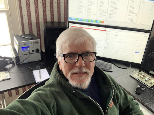
John Siau VP and Chief Designer.
Q: When and how did you come about joining Benchmark Audio?
Between 1990 and 1997, I owned an engineering consulting business where I designed digital video processors, video converters, jitter attenuators, and audio converters for General Electric and Thompson Consumer Electronics. In 1995, I entered into a contract with Benchmark Media Systems to design their first digital audio converter, the AD2004. This 4-channel 20-bit studio A/D converter was the top-performing converter in its day. In 1997, I closed my consulting business and joined the Benchmark team.
Q: Can you tell us a little more about your experience before joining Benchmark?
Secrets Sponsor
It was my love of music and audio systems that prompted me to earn an Electrical Engineering degree at Syracuse University. While pursuing my degree, I acquired an interest in image processing and video systems. As a result, I chose to take my first engineering job working for CBS television at their research lab in Stamford Ct. I spent 15 years designing digital video processing systems, video converters, and video synchronization systems. My experience with low-jitter video synchronization systems served me well as I returned to my first love, designing audio equipment.
Q: Benchmark is one of the few companies that publishes an extensive set of measurements, but you also balance that with subjective testing. Can you talk about the equipment, the listening room, and the process for subjective testing?
Measurements and subjective listening tests serve different purposes. We must select the test methods that are best suited to the device we are designing. From an electronics standpoint, a guitar amplifier and hi-fi amplifier are similar devices. They take a small signal, amplify it, and deliver it to a loudspeaker. Nevertheless, these two devices require entirely different test methods.
If I were designing guitar amplifiers, I would need to rely almost entirely on subjective listening tests. The final product will reflect the listening preferences of the engineers and musicians that crafted the distortion, reverb, and equalization effects on the guitar amplifier. The musicality of these effects cannot be quantified in a meaningful way with measurements. A standard THD measurement is meaningless on a guitar amplifier that is intended to create a musically pleasing distortion effect.
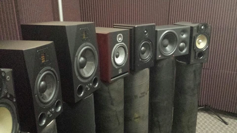
Nearfield Monitor Test in Benchmark’s Listening Room
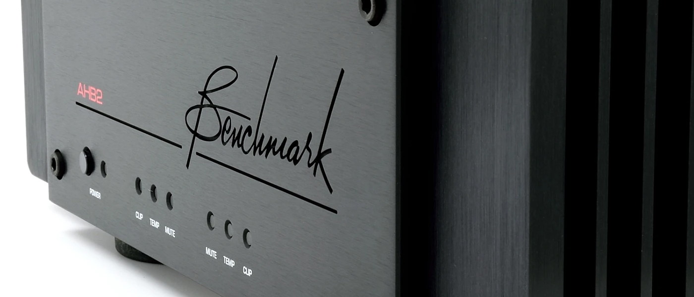
In contrast, the Benchmark AHB2 power amplifier was designed for transparency. It was designed to amplify a recording without changing the way the recording sounds. Ideally, it must not add noise or distortion, nor should it change the frequency response or transient response of the playback system, even when driving a variety of speaker loads over a wide variety of operating levels. Each of these potential defects can be measured and quantified with extreme resolution. Given the measured output power, output noise, output distortion, and efficiency of the speakers being driven, we can show that the AHB2 will not produce noise or distortion exceeding the 0 dB SPL threshold of hearing, even when driving high-efficiency speakers.
When distortion and noise are reduced to levels that are near the threshold of hearing, listening tests become very difficult and inaccurate while measurements can still easily reveal changes that are too small to hear. When the measurements suggest that defects are reduced to inaudible levels, we must still conduct a listening test to confirm that we have not missed something with our measurements. At Benchmark, the listening test is the final exam.
Q: Was there ever a time where you learned something from a subjective test that was not captured by measurements?

Intersample Overs – High Headroom
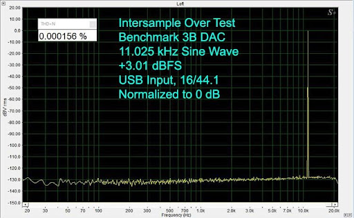
Intersample Over test result, Benchmark DAC3 B from Secrets review
A few years back I was evaluating an asynchronous sample rate conversion chip (ASRC) and I noticed a difference when I switched the chip in and out in a listening test. The music sounded brighter when the chip was inserted. The measurements showed a ruler-flat frequency response with THD+N well below the threshold of hearing in our playback system. Additional measurements confirmed that there was no change in the transient response. Something was happening, but we could not see it in the measurements. Eventually, we were able to prove that the audible difference was caused by the clipping of intersample peaks that exceeded 0 dBFS. The DSP in the ASRC was clipping intersample peaks and this added the impression of brightness. We now have a test signal that we can use to measure this defect which can occur whenever a digital source is upsampled. Starting with the DAC2, all of our sigma-delta D/A converters have an “extra” 3 dB of DSP headroom in order to accommodate the highest possible intersample peaks. The elimination of intersample clipping is a gamechanger, but most of our competitors still seem to be ignoring this problem.
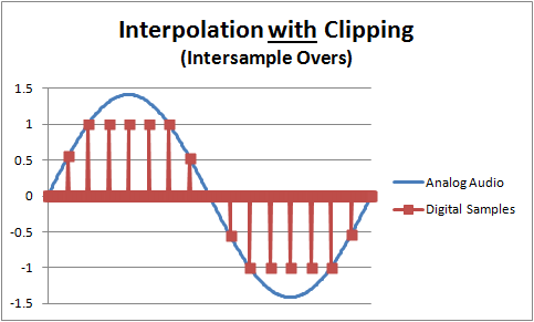
Intersample Overs – Clipped Interpolator
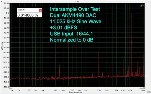
Intersample Over test result, Dual AKM4490 DAC from Secrets review
Q: You conducted some listening tests to determine whether distortion in the “First Watt” was audible. What test material did you use for this, and what did you find?
Class AB amplifiers often produce a small transient every time the output voltage crosses 0 volts. These crossover distortion transients are visible on test equipment, and they raise distortion to a high percentage of the signal when the amplifier is delivering a fraction of a watt. This crossover distortion does not generally show up in THD+N measurements that are made at high power levels, but it becomes the dominant cause of distortion when playing at low power levels. It turns out that most of the sounds we hear in a recording are reproduced using a fraction of a watt. For this reason, I suspected that we should be able to create a simple listening test that would prove that crossover distortion is audible.
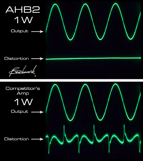
1 Watt Amp Crossover Distortion Comparison
I played a pure 1 kHz tone using 0.01 watt into a speaker with an 87 dB efficiency. The resulting tone was 67 dB SPL, and the distortion was 14 dB SPL. We ran a double-blind ABX test, and the crossover distortion was proven to be clearly audible to most listeners. See https://benchmarkmedia.com/blogs/application_notes/power-amplifiers-the-importance-of-the-first-watt
Q: Crossover distortion and high efficiency have been at odds in various amplifier classes. The AHB2 can eliminate crossover distortion while maintaining high efficiency. You use the patented high-bandwidth feed-forward error correction system to achieve this. Please talk about this system and how it compares with feedback systems typically employed in other amplifiers.
Feedback systems use a recursive process to correct errors after they happen. In the case of zero-crossing distortion, a transient often occurs at the amplifier output before it can be nulled by recursive passes through the feedback loop. In contrast, the feedforward correction system in the AHB2 uses two amplifiers that are passively summed at the output terminals of the amplifier. One amplifier delivers the bulk of the power while a second, low-power, feed-forward amplifier provides a correction signal that instantly cancels the distortion of the main amplifier. The feedforward amplifier is driven by a passive network that subtracts the input signal from the main amplifier output to find the error in real-time. The feedforward system has a much higher correction bandwidth than a feedback system, and it is much more stable when driving reactive loads. Unlike virtually all other power amplifiers, the THD of the AHB2 does not change when the load impedance is changed from 8 Ohms to 4 Ohms, nor does it change when driving difficult reactive loads.
Q: The AHB2 amplifier incorporates THX Audio Achromatic Amplifier technology. When and how did the partnership with THX come about?
Several THX engineers invited me to lunch at an AES conference and asked if Benchmark was interested in building a power amplifier. They didn’t realize that I was already working on an amplifier design. My plan was to build a low-gain class AB amplifier that used a regulated switch-mode power supply. My goal was to produce a 100-watt power amplifier that exceeded the performance of our best D/A converter. To reach this goal, the SNR would need to be better than 130 dB with THD better than -120 dB, while the frequency response would need to extend past 200 kHz. I had been looking at some unique schemes to reduce crossover distortion because it was clear that these goals could not be reached with a conventional class AB design. Much to my surprise, the THX engineers claimed that they had a proprietary technology that would reach these goals. We wrote the performance specifications for the AHB2 at that lunch table, and they agreed to send me a low-power prototype that demonstrated the technology. Over a period of 18 months, the AHB2 went from a series of sketches and specs on a lunch napkin to a finished product. The engineering team included a THX consultant from the UK, another from Canada, and two from the USA. It also included me and two other engineers from Benchmark. The input stage, controls systems, thermal management, protection systems, audio circuit board layouts, and chassis design were all done at Benchmark. Like all of our products, the AHB2 is manufactured and tested in our Syracuse facility.
Q: Linear power supplies have been and remain quite popular in high-end devices. You favor switch-mode power supplies. When and why did you make this switch?
We moved to switch-mode power supplies in 2011 when we introduced the ADC16 16-channel converter for recording studios. The switch-mode power supplies eliminated AC hum and reduced the heat produced by the system. Most importantly, the magnetic fields produced by the unit were greatly reduced and this prevented interference with other devices in audio equipment racks. For a variety of reasons, switch-mode power supplies are vastly superior to linear supplies when building high-performance audio systems.
Q: The AHB2 amplifiers run cool, yet they have heat sinks that are prominent for their size. Are there conditions where these amplifiers get hot?
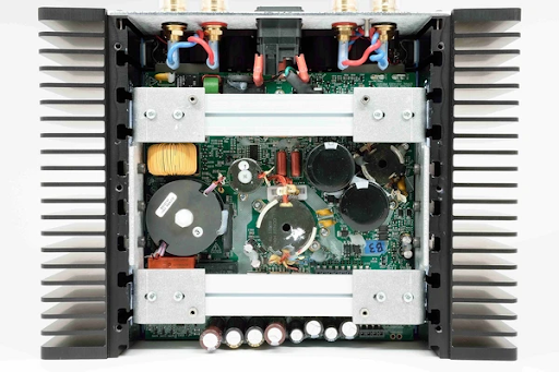
Benchmark AHB2 Amplifier Internals.
The heat sinks on the AHB2 may seem large relative to the physical size of the amplifier but they are actually relatively small given the 390 W bridged-mono power output. Our use of switched-mode power supplies, class-H tracking rails, and low bias current, achieve an overall efficiency that is unrivaled. The AHB2 is a linear amplifier, but its efficiency is close to that of a class-D amplifier. The difference is that the AHB2 does not produce the distortion and high levels of ultrasonic noise that are always produced by class-D amplifiers. Class-D performance measurements can be deceiving because the measurements are made with a 20 kHz brick-wall lowpass filter that removes the ultrasonic noise. That test-equipment brick-wall filter is missing when you connect your speakers to a class-D amplifier. The ultrasonic noise and distortion are sent directly to your tweeters where they can be demodulated back into audible frequencies. For this reason, class-D amplifiers do not sound as good as the measurements would suggest.
Q: What are your thoughts on bi-wiring vs bi-amping?
With most amplifiers, (class-D included) the loading of the bass driver causes distortion at the output terminals of the power amplifier. This distortion is then sent to the mid and high-frequency drivers where it is reproduced as audible distortion. Bi-amping gives the mid and high-frequency drivers an amplifier that is not contaminated with the distortion created by driving the woofer. But … none of this applies with the AHB2. The output terminals of the AHB2 stay distortion-free when driving difficult woofer loads and therefore distortion is not passed on to the mid and high-frequency drivers. For this reason, bi-amping is completely unnecessary with the AHB2. I would love to sell you twice as many amplifiers, but this will not provide any measurable or audible increase in performance.
Bi-wiring can provide a very small improvement with the AHB2 because it removes the woofer loading from the wires that are connected to the other drivers. Our measurements suggest that this improvement is probably inaudible.
Q: There is an abundance of high-priced cable manufacturers. You offer a line of high-quality cables that are reasonably priced. Have you conducted any objective or subjective testing to compare your cables with a high-priced offering?
We sell the same exact cables that we use when testing our finished products before they go out the door. We use these cables because they are extremely reliable and are completely transparent to our measurement equipment. Some alternative cables show measurable signal degradation, and we cannot use these cables for precision measurements. In my opinion, if a cable is not good enough for measurement purposes, we should not be selling it.

Canare L-4E6S Cable Geometry with Braided Shield.
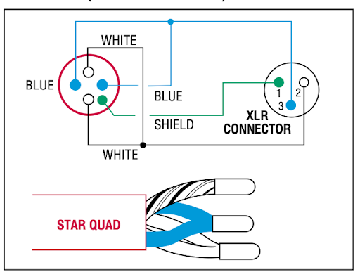
Canare XLR wire to connector diagram.
Q: Canare’s star-quad cables are used in your XLR & speaker cables. Please talk about the benefits of this geometry.
We sell star-quad speaker cables because they minimize the magnetic fields emitted by the cable. Reducing these fields minimizes the chances of interference with other devices and it reduces the inductance of the cable which reduces the high-frequency losses. A speaker cable must have a low resistance and a low inductance. The star-quad construction allows us to reduce the resistance without increasing the inductance.
Q: If the source components and the loudspeakers were far apart, and one had some flexibility in amplifier placement, which option would you recommend: short speaker cables with long interconnects or vice versa?
Short speaker cables and long balanced XLR interconnects, always! If you are forced to use unbalanced RCA interconnects, you have bigger problems.
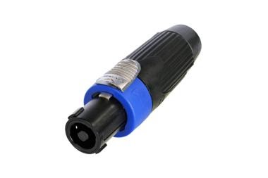
Q: This is the first time I have used Speakon connectors, and I really like them. I wish that more amplifier and speaker manufacturers would offer these connectors as an option. Please talk about your lab tests that showed this connector to outperform other common connector options (spade lugs, pins, and banana plugs).
When we try to measure the THD of the AHB2 amplifier, we can do this easily when using the SpeakOn connectors because they make a reliable low-resistance connection. If we attempt the same measurement with spade lugs, we often have to clean the spade lugs and retighten them to get the same measured performance. The spade connection can produce more distortion than the entire AHB2 amplifier! Forget about spring-loaded banana plugs, these are terrible. However, we have found that we can get very reliable and repeatable performance when using locking banana plugs.
Q: ESS offers several oversampling filters on their DAC chips. Per the Secrets review, you expose one filter which is a “textbook Fast Roff-Off Linear Phase type with excellent attenuation of the first reconstruction tone”.
Was this choice driven by subjective and/or objective evaluation?
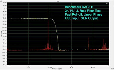
Digital Filter test result, Benchmark DAC3 B from Secrets review
Both.
Some engineers attempt to “improve” the time-domain response by relaxing the brick-wall filter. This appears to work when looking at the square wave response with an oscilloscope, but it changes the sound of the recording by causing phase and amplitude modulation of high-frequency signals. If you relax the response of the filter, transients move toward the nearest clock transition, damaging the time-domain response. Relaxed filters will sound different because they are changing the sound. You can cascade our A/D and D/A converters through many A/D – D/A cycles without causing a change in sound. Try the same thing with a relaxed filter response and it will not work!
As a side note, we are not using the ESS filters, nor are we using the ESS DAC in a conventional manner.
Q: You mention in an article that you operate the DAC2 and DAC3 at a fixed 211 kHz sample rate. This is interesting in that fractional sample rate converters are often avoided. What was the reasoning behind this choice?
We frequency-shift the ESS lowpass filter so that it is always above the Nyquist frequency of the incoming digital audio. We replace this lowpass filter with a sin(x)/x reconstruction filter that is implemented at a gigahertz rate within the ASRC processing. We upsample to gigahertz frequencies, apply the sin(x)/x and then downsample to 211 kHz while applying a proper low-pass filter. The key to this process is the extreme oversampling ratio that we use for reconstruction.
Q: A notable absence from your DACs is MQA. What are your thoughts on MQA, and do you plan to support it?
MQA distorts the time-domain response of the music. MQA is a sonic effect that changes the way a recording sounds. MQA is not transparent and I don’t feel that it belongs in a box that is intended to be transparent. We have seen a rapid decline in requests for MQA. It may go the way of HDCD.
Q: Many folks use software (HQPlayer, Roon, etc.) based sample rate and/or format (PCM<->DSD) conversion upstream of the DAC. Do you see any benefit to this, and if so, is there a preferred sample rate and/or format for your DACs?
We do not recommend upsampling fixed-point digital audio as this will clip intersample peaks. We do this upsampling inside of the DAC2 and DAC3, but we do it with adequate headroom so that clipping cannot occur.
As for DSD, I would never recommend converting PCM to DSD. This is a lossy process; it adds distortion and noise. On the other hand, DSD to PCM conversion is a very straightforward mathematical process. It does not add distortion or noise. The DSD to PCM conversion actually removes ultrasonic noise that could make its way to your speaker if your DAC is not applying a proper DSD low-pass filter.
Q: With the extremely low noise floor and high-precision arithmetic (32-bits) utilized in ESS DACs, digital volume controls have gained popularity. You use this as part of your “Dual-Domain Hybrid Gain Control”. Please talk about the pros and cons of this approach vs the pure analog approach that you use in your line-level preamplifier.
Secrets Sponsor
The DAC volume can be precisely controlled in the digital domain without adding the measurable noise and distortion that would be created by passing through a potentiometer. On the other hand, analog inputs cannot be processed digitally unless we convert the input to digital. Why convert to digital and back to analog just to control the volume? The DAC2 and DAC3 use a traditional potentiometer to control the volume of analog inputs. We sense the position of this control when processing digital inputs. Digital inputs never pass through the pot.
Q: Is there an advantage, or disadvantage, to using a digital volume control in a software player upstream of the DAC? Several players are utilizing 64-bit arithmetic along with sophisticated dither algorithms.
The output of these “32-bit” or “64-bit” volume controls is a 24-bit audio stream. This means that they are mathematically equivalent to 24-bit controls. The internal volume control in the DAC3 has a 32-bit data path to the converter, so it is theoretically better. Nevertheless, the difference between a 24-bit data path and a 32-bit data path is irrelevant. The difference is not audible and is almost impossible to measure.
Q: Do you consider Benchmark products to be at or past the limits of human hearing?
It is very difficult to determine the exact limits of human hearing. These limits vary from individual to individual, and they vary with training, attentiveness, and fatigue. At Benchmark, we try to create a large safety margin between the performance of our products and the threshold of human hearing. “Just good enough” is kind of like “just in time” purchasing with today’s supply line issues. We don’t build bridges that are just strong enough, we build them with a generous safety factor. This safety factor keeps bridges standing if they are overloaded or if our calculations are slightly off.
If there is a generous safety margin between the noise and distortion of the audio electronics and the threshold of normal hearing, then we have created a system that should be transparent to all listeners when the system is ideally configured. The margin of safety is important when the configuration is less than ideal.
Q: Given the performance that you have already been able to achieve, are there any specific areas that you want to improve upon further?
To date, we have been focused on delivering a musical signal between the electrical output of a microphone and the electrical input of a speaker. Electronics can achieve this task with virtual perfection, but most consumer audio products fall grossly short of this goal. Nevertheless, companies like ours that build state-of-the-art electronics have reached the point where we are just building with an ever-increasing safety factor below the limits of human hearing.
If we wish to make meaningful audible improvements, we must reach beyond the speaker terminals. We must explore the possibility of using the electronics to correct unavoidable deficiencies in our loudspeakers and listening environments. The loudspeaker will always be the weak point in the best audio systems.
Q: I’d like to touch on measurement equipment as the performance specifications of your products are pushing the boundaries of what they can reliably measure. Carlo Lo Raso and David Rich touched on this in the review of the Benchmark stack …
“Carlo: It bears repeating that these results are more reflective of the soundcards limits and not the preamp.”
“David: All the SNR figures are state-of-the-art numbers. As are all the other performance aspects of the HPA4 shown in the user’s manual. This makes a nifty bench testing preamp so I suggested that Carlo keep it on the bench and use something else in his audio system. He was not amused.”
For Benchmark to introduce a product that sets a new “benchmark”, you want to be able to measure its capabilities. Are you facing any challenges in this regard?
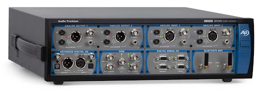
The performance of our equipment closely matches the performance of the APx555B test system. Are we measuring the performance of our product or the test system? Sometimes it is hard to tell. Both represent the current state of the art.
Q: Are any semi-conductor component shortages disrupting production?
In mid-2019, we abandoned any semblance of just-in-time purchasing. We began aggressively purchasing raw parts as a hedge against supply issues. We had no idea what was coming but our hedge paid off! It’s all about having a safety margin.
Q: Does Benchmark plan to introduce any multi-channel products?
Every new product will have at least two channels.
Q: Are there any upcoming products that you can talk about?
The answer to this question would always be no, even if we were working on something.
Many thanks to John Siau for his time and to Rory Rall for facilitating this Q&A.


