
Introduction to the Harman Kardon HK 990 Stereo Integrated Amplifier with Digital Room Correction and Dual Subwoofer Bass Management – Part II
This second part of the HK 990 review examines the signal flows in the HK 990 dual-domain integrated amplifier. This analysis is relevant to all units, including modem AVRs, with a DSP signal processing unit in the main signal path. The signal flow is more transparent in this stereo unit than a 7.1 multichannel unit; so, if you are interested in AVR, please stay tuned
Analog circuit design methods for consumer high-fidelity products date to 1950 with the emergence of reel tape, LPs, and FM. Consumer-friendly discussions of analog component design are found in early (circa 1947) issues of Audio Magazine and early (circa 1951) issues of High Fidelity. Digital recording and CD players arrived at a time that magazines were still somewhat technical. It was not until Dolby Digital (originally called AC-3) started coming off Laser Discs in the mid-1990’s that units with core DSP processors appeared. By that time, the print magazines had de-emphasized technical aspects of design, preferring to focus on
Specifications
- Design: Solid State Stereo Integrated Amplifier
- Power: 2 x 150 watts RMS into 8 ohms @ 20 Hz – 20 kHz, 2 x 300 Watts into 4 Ohms
- MFR: 10 Hz – 100 kHz
- THD: <0.07% at Full Output (8 Ohm Load)
- Analog Inputs: 7, Plus 1 Phono MC, 1 Phono MM, and 1 Balanced XLR
- Digital Inputs: 1 HRS-Link, 2 Optical Digital, 2 Coaxial Digital
- Analog Input Sensitivity/Impedance: 350mV/43k ohms for tuner/CD, 10mV/47k ohms for Phono-MM, 1mV/100k ohms for Phono-MC
- Digital Input Capability: All Standard Digital Formats
- Dimensions: 6.4″ H x 17.3″ W x 17.5″ D
- Weight: 43.2 Pounds
- MSRP: $2,599 USA
- Harman Kardon
- SECRETS Tags: Harman Kardon, HK 990
Part II of this series examines the dual-domain DSP based system at a deeper level than the treatment found in most reviews, but it is not so technical as to leave an interested audiophile puzzled.
HK 990 Looking Inside the Unit

Figure 1 shown above is the HK 990 with its top removed. The key subcomponents are identified with notations along the perimeter of the photo. The power amp (to be discussed in Part III of the review) and its associated power supplies monopolize most of the amplifier’s footprint.
At the front of the unit is a PC board with the control buttons, the volume control-knob (a rotation-sensing device that sends a digital signal when the knob is turned), and the display panel. The electronics on the board, including a microprocessor, are the man–machine interface (MMI). Upon sensing a change on the panel, such as a depressed button, the PC board converts the action
The
The vertical placement of the daughter boards allows external I/O jacks at the rear to be mounted directly on one of the boards. From the rear of the unit, shown in figure 2 below, the locations of three of the boards are apparent. The

The main board interconnects the daughter boards. Almost all the interconnections among the boards are digital. A second on-board microprocessor, the digital volume control, and the
The on-board position of the
Those who find wire to make a sonic difference often forget how much of it is running inside a piece of electronics. Worse, each of these
The main board also contains the power supply regulators. Multiple regulators isolate the different circuit elements. A few sub-regulators are resident on the daughter boards and power some components. With all the power supply regulation on the preamp boards instead of a separate power supply board, there is little wiring of the regulated supplies to the analog components. In front of the main board is its power transformer, which is independent of the power amps.
The big takeaway is the brevity of the analog and regulated power supply interconnections. In addition the long interconnects and multiple RCA jack – plug connections required if you used separate DAC, phono preamp, or power amp are eliminated. In the HK 990 no analog signal leaves from the area of the main preamp board to keep analog connections short. The sole exceptions are the connections to the power amps and headphone jack.
HK 990 Digital Signal Selector, Clock and Data Recovery, Jitter Reduction, and Digital Reconstruction Filtering

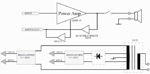
The block diagram of figure 3 above shows the digital input signal flows. The electronics are on the right-most daughter board. Its placement is defined by the optical and coax digital input jacks on the rear panel. The clock and data from the Sony/Philips Digital Interconnect Format (SPDIF) digital inputs are recovered by a TI SRC4392. The chip also functions as the input selector for the digital signals. In an AVR, digital audio data from the HDMI receivers can be selected in this system block. The HDMI receivers are usually on the video board, which is typically at the top of the audio boards in an AVR, which explains the placement of the HDMI plugs atop the rear panel in most AVRs.
The “Phase-Locked Loop” (PLL) is a basic circuit block for the clock and data recovery. Although the SPDIF signal is a serial bit stream, it is coded so the continuous clock signal and the signal that contains the LPCM data can be recovered and separated (the clock and data are shown together in the single thick red wire.). A PLL is on the die of the TI SRC4392. The mechanics of a PLL, its application in a clock and data recovery system, and its ability to reduce jitter, are best left for another discussion. Many texts have been written on Phase-Locked Loop design in both the analog and digital domains. I will try to summarize the essentials in the Primer at some point.
A two-channel (for stereo) asynchronous sample-rate converter (ASRC) resides on the TI SRC4392 to resolve an issue that the recovered clock from the SPDIF signal is not in sync with the clock that drives the DACs. The ASRC also provides digital filtering to remove signals above 20kHz (for the case of a CD) that occur during the sampling process. I discuss ASRCs in more detail below.
A. Maintaining High-resolution Data Through the Digital Signal Selector Front End

1) Bit depth
Figure 4 above shows the audiophile currently has a wealth of high resolution downloadable formats. Whether a modern unit with SPDIF inputs accepts and recovers 24bit incoming data from high-resolution material (DVD-A disc; WAV file; FLAC file) is a less than transparent issue, but one that is significant. Perhaps, more important, is the truncation of the signal as it makes its way from the SPDIF receiver to the DACs. To determine if the 24bits are preserved, the amplitude of a dithered signal is examined as it is reduced from -90dB below full scale (this is called the amplitude linearity test). The in-band signal-to-noise ratio (relative to full scale) is also monitored during the test. The test should occur when the complex DAC process options, such as room correction and bass management, are selected.
For all cases, the signal-to-noise ratios and amplitude linearity are limited by the DAC in the digital path if the 24bit word makes it to the DAC. The product sheet on the HK 990 is unclear about transmission of the 24bit words, but Harman Labs sent me data that indicating the 24bit signal was passed with the DSP in the signal path. The measurements covered the complete analog signal path to preamp out, including the volume control. The HK 990 measurements from Harman labs showed the equivalent signal-to-noise ratio was 19 equivalent bits. A 21bit signal had a -0.7 error relative to its expected amplitude. At 22bit word (-132dB from full scale) had a -1.3dB error. These results are consistent with the performance of the parts used in the HK 990 which will be discussed below.
The signal-to-noise (SNR) ratio of a signal recorded with a 16-bit quantization (98dB) cannot be lowered by signal processing on the received data as some high end companies imply. The number of bits that represent the signal grows as the signal progresses through the digital filters and other digital signal processes. The additional bits occur as mathematical operations are performed on the data. Failure to keep these additional bits may cause distortion and frequency response errors.
Some CDs are recorded with shaped quantization noise. The noise is shaped by removing it from areas of the spectrum that the ear is most sensitive to it. Since the total noise power over the full band must be constant, more noise power is placed at areas of spectrum where the ear is less sensitive to noise. Quantization noise can be shaped only during the recording process. Noise shaping must be done before the data is pressed on the CD. If a noise shaper was not used the process cannot replicated from data coming of the CD.
The noise floor of fast Fourier transform (FFT) developed spectrums shown in audio equipment reports is not the signal-to-noise ratio. The noise floor is the noise over a small frequency band. The size of the band depends on parameters of the FFT. This is shown in Figure 5 below.

2) Sampling Rate
Both the bit depth from the SPDIF digital input and the sampling rate of the high-resolution input must be preserved. The HK 990 accepts inputs with sampling rates up to 192kHz. Like the bit depth, the issue is not whether the SPDIF receiver locks-up to the incoming signal, but the quality of the signal received by the DAC. Activating a function such as room correction may result in sub-sampling (96kHz sampling reduced to 48kHz) in some products.
To identify sub-sampling, the spectra at the preamp output are monitored as a high-resolution file is connected to the input. Sub-sampling has occurred when the spectra above 20KHz are missing.
Again the product information for the HK 990 does not provide the critical information but data from Harman Labs, showed the HK 990 passes the full spectra (45kHz) of a 96kHz input, but this did not increase for a 192kHz input. It is hard to believe anybody could discern the difference.
The SPDIF output mutes on any SACD player when an SACD is inserted. Instead, one must use the analog output on the SACD player and run it to the HK 990 analog inputs. This is not an issue if you use the HK 990 in the digital bypass mode. If you want to enable room correction or bass management the HK 990 must first convert the analog signal from the SACD player back to digital.
An AVR attached to a Universal DVD player by HDMI will transfer a SACD digital data (DSD or transcoded to LPCM) since HDMI encrypts digital data. But dealing with video setup screens on both the AVR and Universal DVD player to enable the link can be complicated, and stereo-centric audiophiles will find this task tedious beyond belief. You need a TV in the room to set things up. The TV can be removed after setup, but may be called back should either the universal DVD player and/or AVR forget its settings as a result of a glitch like a power outage.
The fact that the operability of the HK 990 is not display-dependent is what makes it so wonderful. If you are going to use the room correction or bass management of the HK 990 the best thing to do is use a good CD player and not an SACD player. The CD player will read the CD layer of the SACD and transfer that over SPDIF. The redundant DAC –ADC conversions are eliminated. Given the inability to get high resolution data off an SACD using SPDIF it is clear that high resolution downloads are the way to go in stereo. SACD is important only to the multichannel listener.
B. The Performance and Viability of Proprietary Digital Interfaces
Harman’s proprietary digital interface to its CD players, called the HRS link, provides a return path for the HK 990 system clock to the Harman HD 990 CD player (not shown in the digital input signal flows block diagram above). Tyler Stripko reviewed the HD 990. Figure 6 below shows the special HRS Link multi-wire jack.

As discussed above, digital devices with an SPDIF transmitter have clocks that are asynchronous to the main crystal oscillator on the HK 990. It is impossible to match the crystal oscillator frequency on the device transmitting the SPDIF signal to the crystal oscillator on the HK 990. The HRS link resolves the problem for the HD 990 CD player by forcing the HD 990 CD player to slave the HK 990 clock.
The crystal clock oscillator in the HD990 CD player is disabled when the HRS system is operative. Jitter on the HRS return path is not an issue because the clock that drives the DACs is not recovered from it. The DACs are clocked with the crystal oscillator on the DSP board, which is very close to the DAC.
These types of proprietary links emerged when SPDIF first appeared. Sony’s first solution was an extra SPDIF cable running the clock back to the CD player. Unfortunately, comparable systems of different manufacturers are not fungible. Sony no longer supports the extra SPDIF cable for clock return. Marantz has a BNC input on some of its high-end SACD players marked External Master Clock.
The latest Sony proprietary-link system is called H.A.T.S. for its HDMI connections. The HDMI 1.3 CEC return line controls the data transmission rate to the universal player based on the clock in the AVR. You need a Sony AVR and Sony Blu-ray player that supports H.A.T.S. Pioneer has a nearly identical, but not inter-operative, system called PQLS. Both H.A.T.S. and PQLS are derived from the Audio Rate Control (ARC), which is a new function in version 1.3 of the HDMI spec. Games of deviating from the HDMI spec to create proprietary modes of operation caused big box stores to insist on absolute HDMI interoperability between all suppliers. This appears to have wiped the Audio Rate Control (ARC) off the latest generation of products.
Wedding yourself to these proprietary links can create long term problems. Disk players often require expensive repairs after warranty up to the point where unit replacement is more economical. One is unlikely to find a new unit that supports the old proprietary link. Also consider the circumstances of audiophiles with high-end universal DVD players that had proprietary links when Blu-ray emerged.
Also note that, most units that store and stream high-resolution files only have standard SPDIF outputs. The takeaway is to be certain the equipment you purchase has electronics that insurer the SNR and THD of the analog output is not degraded by impairments of the equipment sourcing the SPDIF signal or impairments from long runs of the SPDIF cable.
C. Working with Asynchronous Clocks without a Proprietary Link in Systems with DSP Processors
As discussed above the clock frequency of a unit with the SPDIF receiver differs from the clock in the unit with the SPDIF receiver. One solution to the problem is the proprietary link. A second alternative is to clock all electronics in the unit with the recovered clock from the source device. The recovered clock must have very low jitter when it clocks the DAC or SNR and THD will be degraded. Methods are available to achieve this. Note direct measurements on the clock sent to the DAC in the presence of jitter at the input can guide the designer in optimizing the system. It is possible for a reviewer to open up the box and make these measurements but I strongly dislike this. Any effect of clock jitter should be observable at the analog outputs of the unit in the form of increased noise or new distortion components.
In units like the HK 990, and most AVRs, the digital electronics in the unit (often multiple DSPs) are clocked by a local crystal oscillator. A digital circuit block, called an Asynchronous Sample Rate Converter (ASRC), is used. The recovered clock and LPCM data (one channel) from the SPDIF receiver enters the ASRC. In addition, the local clock oscillator on HK 990 or AVR, enters the ASRC.
The ASRC processes the incoming LPCM data and the LPCM data leaves the chip is not the same as what came in. To understand this, let us look at a conceptual ASRC. An ideal DAC is clocked with one oscillator. The DAC, after reconstruction filtering, drives an ideal ADC clocked by a different oscillator. This conceptual ASRC is illustrated as a block diagram in Figure 7 below.

Note that the ASRC does not produce a clock it just provides a mechanism to interface the LPCM signal between to clocks that already exist. Clearly, the LPCM data entering the ideal DAC is not the same as what is exiting the ideal ADC if the clocks are different frequencies.
The ASRC can take in a clock with jitter on the LPCM input side and a jitter-free clock on the LPCM output side. Does this not imply all the jitter has been rejected. No! The effects of the jitter (increased SNR and distortion above what is measured with jitter-free clocks) may be present on the LPCM data exiting the ASRC. The worst-case situation is the mixed-signal example shown above. The DAC rejects none of the jitter on the clock driving it All the distortion and noise resulting from the jitter is now part of the LPCM data leaving the ADC.
ASRCs, in practice, are fully digital and have no internal DAC or ADCs. A fully digital ASRC interpolates (up samples) the LPCM input data to a very high sampling rate, which is then re-sampled at the output clock’s rate. The system just described is impractical to integrate. Digital designers have developed systems that can emulate the functionality in less silicon.
Artifacts from the design limitations for a practical all-digital ASRC are small frequency response variations and distortion components in the LPCM data at the output. These arise in the process of the sample-rate conversion (no jitter on the clocks). The distortion components may not be harmonically related to the incoming tone encoded in the LPCM. The distortion and frequency response deviations are called out in the ASRCs data sheet for standard products like the TI SRC4392 used in the HK 990.
Distortion and frequency response variations can be measured on LPCM coming out of the ASRC; indeed, modern analog test equipment first converts the signal to LPCM before analysis. Different graphs are supplied for common sample rate conversions in audio products.
A practical fully-digital chip ASRC will reject some jitter. A section of the digital circuitry estimates the frequency ratio of the two clocks. The rate at which this estimate can change is limited. Robert Adams, who created the first ASRC for an audio application, points out the estimate is “computed using thousands of past input and output sample clock events and is therefore immune to small perturbations in the arrival time of any clock edge.”
The ratio estimate is less affected the faster the clock edges arrival time changes. Some ASRC data sheets offer a graph that demonstrates how fast the clock edge arrival times must vary for the ratio estimator to become insensitive to it. This graph cannot replace graphs showing SNR and distortion increase with different types of jitter present on one of the clocks. I have not seen an ARSC data sheet with these measurements.
Without a SNR and distortion measurements at the output of the ARSC in the presence of clock jitter at one of the clocks, a relative evaluation of two ASRC designs is not possible, and I cannot identify from the current data sheets which ARSC is best with respect to jitter rejection. Valid comparisons between standard products are obscured even further because the designer customizes the ASRCs performance by selecting internal options.
Murkier still, there are no standard tests that simulate the statistics of jitter that might be on the recovered SPDIF clock presented to the ASRC. First the test clock must simulate the statistics of jitter of the oscillator that is part of the PLL in the SPDIF receiver. At the SDPIF receiver recovered clock jitter statistics can change dependent on the LPCM data being transmitted (recall the clock and data are encoded on the single SPDIF cable) This is called data dependent jitter. Some LPCM test patterns have been proposed that are said produce worst case data dependent jitter but no consensus exists on which patterns are worst case. Recovered clock jitter will increase as the SPDIF signal passes through longer lengths of cable. Again this jitter may have different statistics.
For those who want to know more about jitter, how it affects DACs, and how an ASRC operates, please consider an article written by Robert Adams. It is published on pages 11 -22 of Issue 19 (Spring 1994) of The Audio Critic. The complete issue is available as a free PDF download on The Audio Critic website.
ASRCs may be found as part of a DSP chip (eight are in the Analog Devices ADSP-21469 designed for use in AVRs). An ASRC can be executed as software and implemented as an independent DSP or a DSP that performs multiple processing functions.
The service manual provides clues about the performance of the analog and data converter stages that can predict the performance when device measurements are made at the units rear panel as I will demonstrate in Part 3 of the review. In contrast, the parts used in the product provide no clue to the jitter rejection. Only special measurements at analog outputs will expose how much the jitter is attenuated. Without standardized tests I have chosen not to report on SNR and distortion impairments at the analog output as a result of jitter on the SPDIF input.
D. Digital Filtering of the LPCM Signal
An ASRC may provide the LPCM data at its output at a higher sampling rate than what came in. For example, LPCM data from a CD player arrives at 44.1kHz input, but could leave at 192kHz.
Artifacts from the sampling process, called images (shown in figure 8 below), are removed during the process of increasing the sampling rate.

For a band-limited 20kHz analog signal sampled at a rate of 44.1kHz samples/sec (fs) the spectra appear around 0Hz (desired signal) as well as from 24.1kHz to 64.1kHz and then repeat around multiples of 44.1kHz. The repeating spectra are the stop-band images from the sampling process. For a 20kHz signal (fB), the right side of the first image (often called the folded frequency) is close-in at 22.1kHz (44.1kHz – 20kHz). The suppression of the stop-band images allows the sampled signal to better represent an analog signal sampled at 44.1kHz. Information lost from band limiting of the signal before the sampling process during recording cannot be restored although some manufactures try to imply this. For high resolution files fs will be between 88.2 – 192kHz. The maximum frequency that can be recorded (fB) can also be extended since the right side of the first image will be at a higher frequency.
How well the ASRC removes the images is again dependent on its design. The process of attenuating the stop-band images of a sampled signal and increasing the sampling rate digitally often takes on interesting names from each company. For the HK 990, it is named the fourth-generation of the Real Time Linear Smoothing system (RLS IV). To repeat although the sample rate has been increased, no information about the sampled signal above 20kHz (for the case of a CD player) can be recreated. Instead, what has been accomplished is the removal of the folded tones in the digital domain to obviate removal later by complex analog filters.
In the absence of an ASRC a standard digital filter up-samples the incoming signal at an integer rate of 2, 4 or 8 and removes the stop band images. The filter may by as implemented as DSP software or it may be done in digital hardware. Like the ASRC, the filter leaves small frequency response variations and distortion products (folded tones not completely removed, for example). The design of the filter determines how well it performs in the frequency and time domains. Sometimes a standard digital filter may be placed after an ASRC to reduce the stop band images further.
Often the digital filter used is in the DAC chip itself, not an external block. The internal DAC filter is bypassed by the HK 990 in favor of the ASRC and perhaps additional filtering in the DSP block. The performance of the filter in the integrated circuit DAC may vary. Filters with poorer performance have more amplitude variation across the audible band, although this is normally dwarfed by the variation from the analog circuits. The other difference in filter performance is the attenuation of the folded spectra.
In general, the performance of the digital filter in the integrated DAC correlates with the THD and SNR performance. For superior performance in the mixed signal domain, more silicon area is made available for the digital filter because the improvement in analog noise floors can expose problems with the simpler digital filters.

Designers may design custom ASRCs and up-sampling filters to gain a performance advantage over generic products. Typically, the designer will do this in software using a standalone DSP. Some designers develop the filters to achieve performance objectives in the time and/or frequency domains. The custom DSP implementation is the most expedient way in which a designer can distinguish the performance of his product from the competition. This assumes a DAC has been selected with state of the art performance. In addition analog components connected to the DAC must be selected so they do not degrade the performance of the DAC. The Harman HD 990 CD player used proprietary software for the ASRC and up-sampling filter. Harman calls the system RLS III. An Analog Devices Blackfin DSP (Package photo shown in Figure 9 above, ® Analog Devices) was selected to execute the custom DSP code.
Like jitter, folded tone suppression must be measured. Examining the unit provides no clues, especially if the filter has custom crafted code for a DSP. Unlike jitter standard tests exist. For example a full scale 20kHz LPCM signal on a CD.
Analog Input Signal Flow of the HK 990

The electronics represented on the block diagram (Figure 10 above) are located on the left-most daughter board as dictated by the placement of the analog inputs on the rear panel.
Relays, not silicon switches common to most AVRs, drive the function selector for the analog inputs. As can be seen, the signals from the phono board are also routed to the relay bank. Each relay is a fraction of an inch from the analog input jacks on the back. The MMI at the front of the unit activates a relay based on the user’s selections. In the direct mode, the output of the relay is connected to the digital volume control. Some posters in the AVS forums have been complaining about the clicking sound of relays in higher-end equipment. They should stop and think: does one just want the signal to be transmitted across a metal strip or would they rather the signal was transmit across a MOSFET transistor with significantly higher resistance that varies with the incoming voltage. Relays and the associated drivers are more costly than a silicon switch. Reliability of a relay and the associated driver circuitry is the only downside.
For DSP functionality to be enabled, the analog inputs must be converted to digital by an Analog-to-Digital Converter (ADC). In the HK 990, the ADC is a Cirrus CS5361, one notch down from top of the line Cirrus ADC. The bit-equivalent signal-to-noise ratio (SNR) is 17.5 bits worst case (A-Weighted). The bit-equivalent distortion is 16.5 bits worst case at 1kHz with an input signal 1dB below full-scale.
Even on expensive AVRs, the ADC is often a low-grade single-ended part, a kludge by AVR designers who assume the only analog signals entering emanate from cassette decks and VCRs. They completely forget about converting a phono signal, which needs a high-quality converter to prevent sonic degradation.
The tape output path has its own function selector and ADC. This supports the option of listening to one input and recording another. I elaborate upon the tape output path in Part 3.
HK 990 Digital Signal Processing and DAC Block

The core of the HK 990 is the digital signal processor (DSP) and DAC that converts the DSP’s computations to analog. The function shown in the block diagram directly above (Figure 11) is on the same board as the digital selector block discussed previously.
The switch at the left selects the LPCM data from the digital input board or the analog input board. In the case of the analog input board, the analog signal was converted to LPCM by the Cirrus CS5361 ADC before arriving at the switch.
The DSP in the HK 990 is a TI Aureus TMS320DA708. For room correction, the DSP has two different functions to perform. First, the room must be measured. The DSP generates the test signals to be sent to the speaker, records the resultant acoustic response of the room sent to the microphone (in the room-calibration mode, the microphone signal is routed to the ADC on the analog board), and generates the filter coefficients for room correction. Room-correction systems with on-board DSP can take several minutes to calculate the coefficient because the DSP is not designed to execute these types of off-line computations efficiently. The microcontroller on the main board is also involved in coordinating the room calibration process and transmits information to the MMI board so the user knows where to place the microphones and when it is safe to move them to a new position.
In normal operation, the incoming digital signal passes through the filter bank that is loaded with the room correction coefficients calculated as explained above. A significant part quality of the room correction depends on how well the coefficients are determined during the room measurement process. Systems that do the calculations with an external PC have an advantage.
The other metric of room correction quality is how much filtering can be accomplished in real time by the DSP. Each filter section requires multiplication and addition (subtraction) operations. The faster the DSP operates, more Multiply-Accumulate (MAC) operations can be applied to each sample. MACs (or FLOPS (floating-point operations per second), not the more familiar Million Instruction per second (MIPS), are one of the benchmark for DSP performance. The latter is the typical benchmark for microprocessors
Different DSPs have different MAC ratings that correlate with price. MACs are not the only consideration for a DSP engineer since each DSP has specialized instruction sets and data paths that also affect performance. For example, the DSPs designed for use in AVRs would drain a cell phone battery in a few minutes. Development tools differ significantly for different DSPs and different applications. Without good tools, it may be impossible to complete the design job on time.
In the HK 990, the DSP processor does two other jobs. First, is the bass management function. This will monopolize some of the available MACs. Recall the HK 990 supports two subwoofers that double the MACs for the room correction computations at the subwoofers (calculation requirements for the main channels are unchanged). Second, is to simulate the analog bass and treble control.

The fourth daughter board is a general purpose platform on which the TI Aureus TMS320DA708 DSP chip (Chip package logo shown in Figure 12 above; ™ Texas Instruments) and the associated RAM and Flash memory reside. It is unclear how Harman harnesses the board’s computer power in the HK 990. They could have just used the code from the top of the line AVR (AVR 7550HD), leaving most of the computational power of the chip, which would normally process the other unused six channels in AVRs.
Alternatively, the resolution of the room correction system could have been improved over the AVR 7550HD, or the designers could have introduced high-order crossovers to enhance the bass management system. Unfortunately, my measurements of the bass management system indicate it is no better than the ones found on AVRs.
The DSP in an AVR has other chores aside from eight channels of room correction, bass management, and optional jitter suppression (soft ASRC):
- The decoding of all possible multichannel audio formats entering on the HDMI line to LPCM (example: DTS Master Audio)
- Volume compression (example: Dolby Volume)
- Surround synthesis function (example: SRS Circle Surround)
- Conversion of 5 or 7 input channel inputs to 9 or l1 (example: DTS Neo X).
- Signal processing to improve the sound of low bit rate compress signal such as MP3
- THX equalization
- Virtual Presence Speaker function
- Hall simulations using delay and reverb (often now expanded for game modes)
To accommodate the myriad functions, two or three DSPs may be present in an AVR. Often two DSP are placed on a silicon die and enclosed in a single package. Much of the code outlined above for an AVR may be proprietary to the DSP vendor. The company designing the AVR picks what options they want and thus have little added DSP coding. The more options, the more MACs used. Low-end AVRs with 5.1 outputs and simple room correction may use one low cost DSP, while a more elaborate unit may employ a trio of DSPs. The DSP vendor profits not only by supplying more DSP hardware, but also via fixed and variable (per unit) fees for the company’s code blocks.
AVR manufacturers may develop code for a custom room-correction system, though some DSP suppliers also supply room-correction code. Many Sherwood units and the lower-priced Harman AVRs have room-correction algorithms sourced from Cirrus. Given the substantial research and development effort, an AVR manufacturer hopes to recover these costs in a custom implementation by producing better quality sound when the room correction is selected. In turn, the improved standard of performance should enhance sales.
HK 990 Digital to Analog Conversion (DAC)

The block diagram of the DSP board is repeated as Figure 13 above with the Subwoofer DAC highlighted in the yellow box. All digital-to-analog converters are driven by the DSP. It is typical to place the DACs on the same board as the DSP since a significant amount of wiring runs between the two (a single wire is used in the diagram above to represent 3 wires).
The HK 990 can deal with two independent subwoofers. The DSP connection to the stereo subwoofer channel is typical of a DAC connection in an AVR. In the HK 990, the stereo DAC for the subwoofer is the Wolfson XMB8740. The Wolfson XWM8740 is below the DSP in the previous figure.
In an AVR, the number of DACs connected to the DSP depends on the number of main and subwoofer channels offered. The plethora of DACs complicates the block diagram, but nothing fundamentally changes. Typically, in a 7.1 channel AVR, eight channels must be converted with four stereo DACS.
The Wolfson XMB8740 DAC is above average. The bit-equivalent signal-to-noise ratio (SNR) is 18 bits worst case (A-Weighted). The bit-equivalent distortion is 15.5 bits worst case at 1kHz at full-scale. This is more than adequate for the subwoofer channels exceeding the performance of DACs for the main channels in most AVRs.
Some may find it strange that each data converter is sourced from a different vendor (Cirrus, AKM, Wolfson and Analog Devices). The DSP is from Texas Instruments, who also manufactures audio DACs. In general, large electronics enterprises (not just in the audio space) do this to ensure no single IC company commands significant pricing leverage and, at the extreme, ensures no vendor is indispensible. This makes life difficult for smaller companies who have no pricing power given their small order quantities.
HK 990 Improving Performance by Operating a Pair of DACS in a Balanced Configuration

The HK 990 (and HD990) handles the main channel DSP/DAC interface in a novel manner. Figure 14 above provides the block diagram details in the yellow box. One channel is converted by two DACs in the single Analog Devices AD1955 package (on the left side of the block diagram). Normally the AD1955 is a stereo DAC, but in the HK 990 it will convert only one channel. This is accomplished in the fully balanced configuration. In a balanced circuit, one input is the inversion of the other. Instead of sending stereo data to one of the AS1955 the DSP sends the same LPCM data both in phase and out of phase. Again a digital wire in the diagram above to represent 3 wires.
After each DAC in the AD1955 completes its analog to digital conversion, there are two balanced analog outputs. In the analog stages that follow the DACs (not shown in the block diagram), the balanced signals are subtracted from each other to form a single-ended output. In the process of converting the balanced analog signal to the single-ended output, some distortion produced by each DAC in the AD1955 package is partially canceled. Using two DACs for one channel also reduces the noise level at the DAC’s output.
The bit-equivalent signal-to-noise ratio (SNR) of the AD1955 in the mono mode is 18.6 bits equivalent bits worst case (A-Weighted). The bit-equivalent distortion exceeds the chip’s stereo specification of 16.7 bits worst-case at 1kHz at full-scale. The data Harman Labs sent me exceeded this at the preamplifier output with all the additional analog electronics adding noise to the measurement.
The balanced DAC configuration of the HK 990 is atypical for an AVR. If used at all, the balanced configuration would apply only to stereo channels.
HK 990 Backend Analog Circuitry

The diagram above (Figure 15) shows the remaining circuits that are in place before the preamp output. We have already discussed the interface of the DSP to the DAC. Next, the reconstruction filter must remove the high-frequency folded spectra from the sampling process. Most of the filtering of the folded spectra was performed in the digital domain as was discussed above.
Below (Figure 16) is the simulation of the how second-order analog reconstruction filter in the HK 990. Only residual high frequency clock noise is removed by this filter. The filter is down -0.5db at 45 kHz (approximate maximum inband frequency for 96 kHz sampling). Since it is a low Q 2nd order filter it is down only 20dB at 600 kHz.

The next block in the diagram is the digitally-controlled volume control. Recall the volume knob on the front panel is a component of the MMI and is not a genuine potentiometer. As it is turned, the microprocessor senses movement and sends a formatted digital signal to the digitally-controlled volume control requesting a change in the tap position.
As shown in the diagram, the digital volume control does not connect to the preamp outputs. A buffer isolates the volume control output from the load at the preamp output and power amp inputs. A relay is in the signal path to prevent loud popping sounds that occur as the unit powers up or down from being transmitting to the output. The buffer and relay are also as close to the preamp outputs as possible.
Conclusions
We ended at the analog preamp out. Our journey through the HK 990 DSP-centric integrated amplifier has concluded. While the unit’s design requires a multi-disciplinary approach and hundreds of parts, the basics of the design at the block-diagram level is reasonably straightforward. Along the tour, I highlighted the similarities of the HK 990 to an AVR. With the HK 990, there were only two channels with which to deal. We also did not get lost in the weeds with issues related to video boards.
Part III drills down at the circuit level where patterns are very different from an AVR. It is at the circuit level where one gains an appreciation of the unit’s cost. If you want to revisit Part I of this HK 990 three-part series….