Below is an overview of the key mathematical aspects.
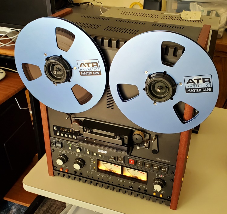
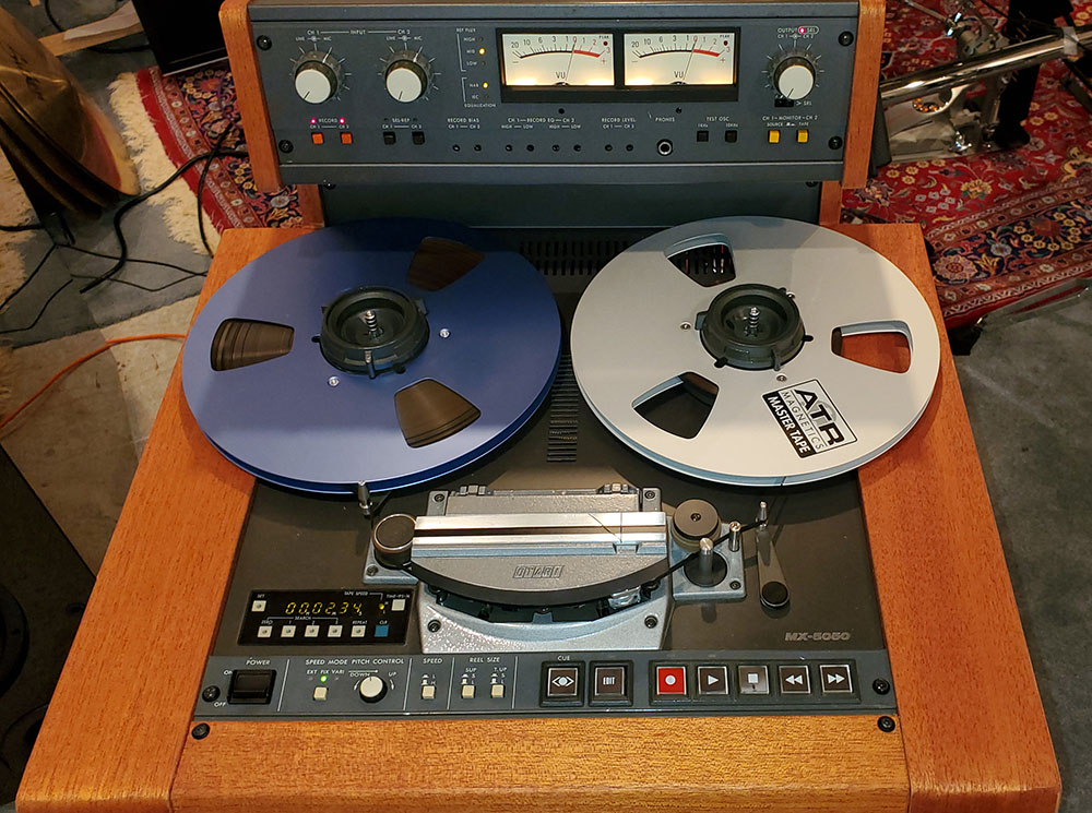
Analog tape, like vinyl, has made a comeback in recent years. Reel-to-reel (RTR) decks have been on E-Bay for several years at high prices. They are getting harder to find because they are being bought up, and the supply of old vintage decks is limited. A few companies are making new decks, but the prices are very high.
A few years ago, I published a blog entitled, “How Reel-to-Reel Tape Decks Work and My Experiences with Purchasing and Repairs…”
Although it is detailed, one of the things that is not in that article is the mathematics of tape recording and playback.
I am now putting that mathematical information in the current technical article, along with additional technical analog tape facts and comparisons to digital recording.
First: How is Analog Audio Magnetic Tape Manufactured?
The manufacturing of audio magnetic tape involves several intricate steps to create a high-quality medium for recording and playback. Here’s an overview of the process:
- Substrate Preparation
- Material Selection: The base layer of the magnetic tape, known as the substrate, is usually made of polyethylene terephthalate (PET) or other similar plastic materials. PET is preferred for its strength, flexibility, and stability.
- Film Production: The substrate is manufactured by extruding and stretching the PET film to the desired thickness (typically a few micrometers).
- Magnetic Coating Formulation
- Magnetic Particles: Tiny particles of magnetic materials, such as iron oxide (Fe₂O₃) or chromium dioxide (CrO₂), are prepared. For high-end applications, metal particles or barium ferrite may be used.
- Binder: The particles are mixed with a polymer binder that helps them adhere to the substrate. Common binders include polyurethane or other synthetic resins.
- Additives: Lubricants, dispersants, and anti-static agents are added to enhance performance and durability.
- Coating the Substrate
- Coating Process: The magnetic coating mixture is applied to the PET substrate using precision coating techniques, such as gravure coating or knife coating. The coating must be uniform to ensure consistent recording and playback quality.
- Drying: After coating, the substrate passes through a controlled drying process to evaporate solvents and solidify the magnetic layer.
- Surface Treatment
- Calendering: The tape is run through heated rollers under pressure to smooth the surface and compact the magnetic layer, which improves signal quality and reduces wear on playback heads.
- Polishing: Additional surface finishing may be performed to minimize roughness.
- Back Coating (Optional)
- For certain tapes, a back coating is applied to the non-magnetic side of the tape. This layer reduces static electricity, enhances winding performance, and prevents slippage.
- Slitting
- The wide roll of coated tape is slit into narrower strips of various widths depending on the intended format (e.g., cassette tapes, reel-to-reel, or professional audio formats).
- Quality Control
- Inspection: The tape undergoes rigorous testing for defects such as coating irregularities, scratches, or contamination.
- Performance Testing: Parameters like frequency response, signal-to-noise ratio, and magnetic properties are tested.
- Spooling and Packaging
- The tape is wound onto spools, reels, or cassettes.
- Packaging includes protective covers, labeling, and sealing for distribution.
Advances in Manufacturing
Modern magnetic tapes may incorporate advanced materials and manufacturing techniques, such as thinner substrates for increased data density or advanced magnetic formulations for enhanced fidelity and longevity. However, with the rise of digital recording, magnetic tape manufacturing is now mostly limited to niche applications and archival storage.
Now, the Math
- Signal Representation
Analog audio signals are continuous-time signals represented mathematically as x(t) where t represents time. These signals are typically sinusoidal or can be decomposed into sinusoidal components using Fourier analysis.
-
- Fourier Transform: Used to analyze the frequency content of the audio signal:
- Magnetic Field and Flux
The recording process relies on the relationship between the current in the recording head and the magnetic field applied to the tape.
- Faraday’s Law of Induction: Describes how a changing current I(t) produces a magnetic flux Φ(t): Φ(t)=L⋅I(t) (Φ is the Greek letter phi)
where L is the inductance of the recording head.
- Magnetic Remanence M(t): The residual magnetic flux in the tape is proportional to the current but exhibits hysteresis, a nonlinear relationship described by the tape’s B-H curve.
- Nonlinearity and Hysteresis
The B-H curve of magnetic materials involves nonlinearities, meaning that the relationship between the magnetic field H and the magnetic flux density B is not linear.
- Mathematical models of hysteresis often use Preisach or Jiles-Atherton models, which involve integrals and differential equations.
- Bias Signal
A high-frequency bias signal (typically a sine wave) is added to the audio signal during recording to linearize the magnetic response and reduce distortion.
-
- The bias signal can be represented as:
where fbias is the frequency of the bias signal, and A is its amplitude.
- This process involves modulation theory, as the signal is modulated by the bias frequency.
- Signal-to-Noise Ratio (SNR)
The quality of tape recording depends on the signal-to-noise ratio (SNR), which is influenced by tape speed, magnetic particle density, and noise.
- SNR is defined as:
- Filtering and Equalization
Playback involves compensating for the frequency response of the tape and recording process.
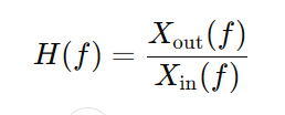
Equalization applies filtering using transfer functions to flatten the frequency response:
- Wow and Flutter
Tape speed irregularities introduce frequency modulation (wow and flutter), which can be analyzed using modulation theory and statistics to quantify deviations.
- Erasure
The erasure of recorded signals relies on applying a decaying high-frequency signal, often modeled as an exponential decay:
- Phase and Time Delay
The playback head interprets magnetic flux changes, and phase delays may occur, analyzed using:
where Δϕ is the phase delay, ω is angular frequency, and Δt is the time delay.
In summary, analog tape recording and playback involve a mix of linear algebra, calculus, differential equations, Fourier analysis, and nonlinear system dynamics to model, analyze, and optimize the processes of recording and reproducing audio signals.
In Practical Terms
The voltage applied to the recording head of a reel-to-reel tape deck at 0 dBVU depends on the specific design and calibration of the tape deck. However, the general principle involves the following:
Understanding 0 dBVU
- 0 dBVU is a standard reference level used in analog audio recording equipment, equivalent to a voltage of 1.228 V RMS in professional audio recording systems (in a digital recording studio, this is calibrated to be equal to +4 dBu and minus 18 dBFS).
- In analog tape decks, this reference level corresponds to a specific magnetic flux level on the tape (e.g., 185 nWb/m for many professional decks – nWb is nanowebers). The Weber is an international unit of magnetic flux (magnetic strength), and for analog tape, the flux is expressed as nanowebers per meter.
Voltage to the Recording Head
The voltage applied to the recording head is not directly equal to 1.228 V because:
- Recording Amplifier Gain: The signal from the line-level input (0 dBVU) is amplified by the recording circuitry before being sent to the recording head.
- Impedance of the Head: The recording head has a certain inductance and resistance, which affects the voltage required to produce the desired current.
- The voltage applied to the recording head is designed to create the necessary current to magnetize the tape at the reference level. The current is determined by the head’s impedance and the magnetic flux requirements: Vhead = Ihead x Zhead, where:
- Ihead: Current through the head
- Zhead: Impedance of the head, which depends on frequency (inductive reactance (ZL=2πfL) and resistance.
Typical Values
- For many reel-to-reel tape decks, the recording head operates at voltages in the range of 100 mV to a few volts, depending on the tape speed, head design, and reference flux level.
- The exact voltage is tailored to ensure the current through the recording head induces the correct magnetic flux density on the tape.
Considerations
To determine the precise voltage applied to the recording head:
- Refer to the specific service manual or technical documentation for the tape deck.
- Measure the output voltage of the recording amplifier with an oscilloscope or multimeter.
In summary, the voltage applied to the recording head is derived from the tape deck’s internal amplification circuitry and is optimized to achieve the reference magnetic flux corresponding to 0 dBVU. While the input signal is 1.228 V RMS at 0 dBVU, the actual head voltage will be lower or higher depending on the deck’s design.
What Changes Occur in the Iron Oxide Particles on Magnetic Tape When the Tape Head Records on the Tape?
When a magnetic tape records audio, video, or data, the recording process involves changes in the iron oxide particles on the tape’s surface. These particles are the medium for storing information magnetically. Here’s what happens:
- Magnetization of Particles
- The iron oxide particles, typically magnetite (Fe₃O₄) or gamma-ferric oxide (γ-Fe₂O₃), are ferromagnetic.
- The recording head generates a magnetic field proportional to the electrical signal it receives.
- This magnetic field aligns the magnetic domains of the iron oxide particles in a pattern that corresponds to the signal’s waveform (audio, video, or digital data).
- Change in Magnetic Orientation
- The particles themselves don’t move; instead, their magnetic domains reorient.
- The orientation of these domains (direction and intensity) varies with the strength and polarity of the recording signal.
- This process imprints the signal as a series of tiny magnetic fields across the length of the tape.
- Permanent Magnetization
- Once the tape moves past the recording head, the magnetic orientation becomes “frozen” or permanent due to the coercivity of the material.
- These patterns can be read later by the playback head, which senses the magnetic changes and converts them back into an electrical signal.
- Physical Changes
- While no significant physical alteration occurs to the particles themselves, repeated recording and playback may cause gradual wear or demagnetization of the tape, leading to signal degradation over time.
- Signal Representation
- Analog recordings: The strength and polarity of the magnetization vary continuously to represent sound or image waveforms.
- Digital recordings: The magnetization alternates between discrete states representing binary data (0s and 1s).
In summary, the recording process realigns the magnetic domains of iron oxide particles to encode information, leaving a lasting magnetic pattern on the tape.
What About the Bias Voltage and Bias Frequency on the Recording Head?
The bias voltage and bias frequency in a reel-to-reel tape deck depend on the specific design and intended use of the deck, such as its tape speed, tape type, and whether it is a consumer or professional device. Below is an explanation of these parameters:
Bias Voltage
The bias voltage refers to the amplitude of the high-frequency AC signal added to the audio signal during recording. This signal is used to linearize the magnetic response of the tape and reduce distortion.
- Typical Values: The bias voltage is generally in the range of 50 to 150 V peak-to-peak but varies depending on:
- The inductance and impedance of the recording head.
- The type of tape being used (different formulations require different bias levels).
- The deck’s design (professional decks often have adjustable bias settings).
- Current Considerations: Since the recording head is driven by current, the bias voltage must be sufficient to generate the required bias current through the head.
Bias Frequency
The bias frequency is the frequency of the high-frequency signal, which is typically beyond the range of human hearing to avoid audible interference with the recorded audio. During playback, a notch filter can be used to remove the bias frequency peak that would otherwise be present in the output.
- Typical Range:
-
- 40 kHz to 150 kHz for most reel-to-reel tape decks.
- The exact frequency is chosen to be well above the highest audio frequencies (20 kHz) but not so high as to cause inefficiencies due to the inductive reactance of the recording head or excessive tape losses.
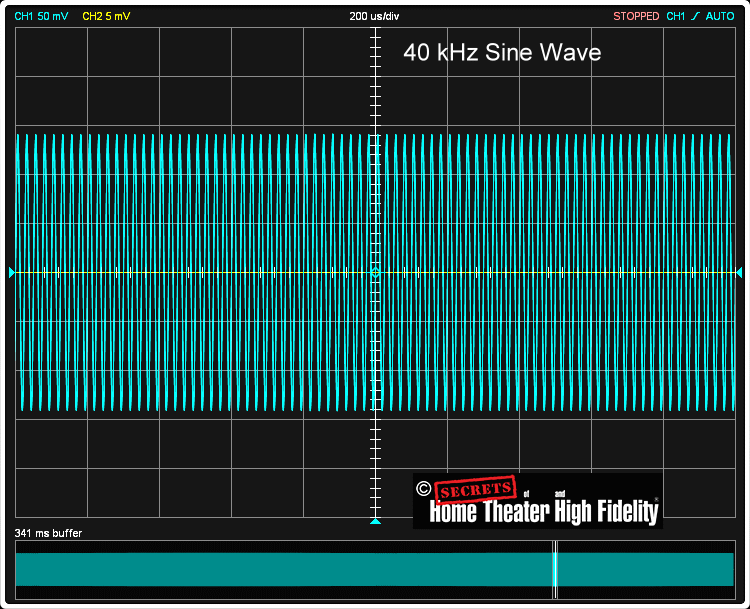
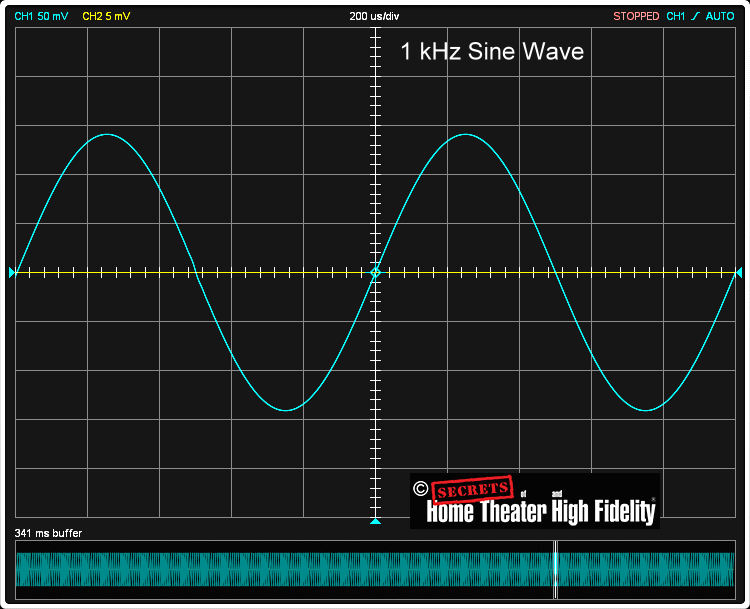
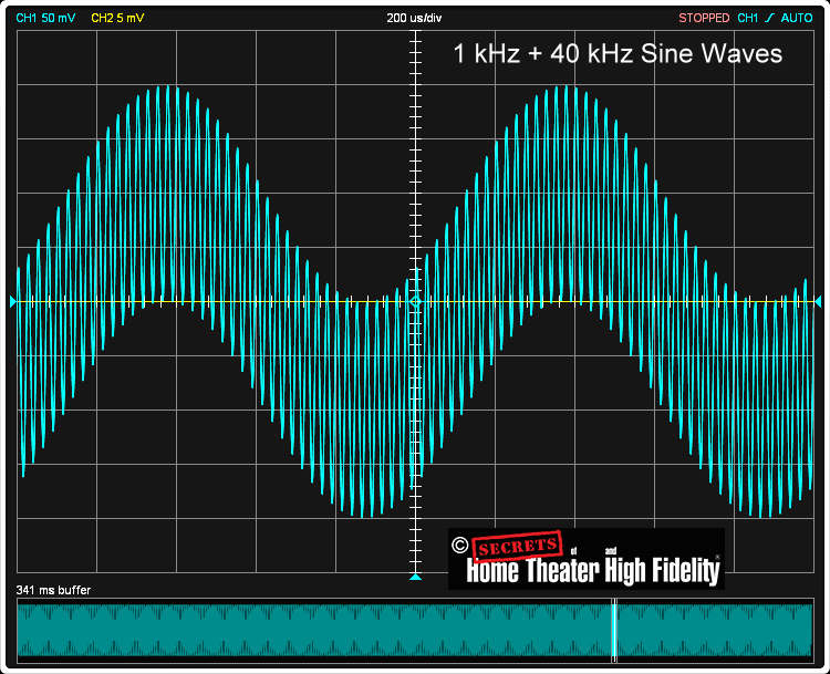
- Here are three spectra. The first one, below, is a 40 kHz sine wave bias voltage frequency. All three figures are from “How Reel-to-Reel Tape Decks Work and My Experiences with Purchasing and Repairs…” Secrets, (2022)
-
-
- The second one, below, is a 1 kHz sine wave audio frequency (part of the music you are listening to).
- And the third one, below, is the combination of the bias frequency and the audio frequency. During playback, the bias frequency is removed with a notch filter (a very narrow EQ attenuation at that frequency).
-
- Factors Affecting Bias Frequency:
- Tape Speed: Higher tape speeds allow for higher bias frequencies, while lower speeds may require lower frequencies to ensure proper signal recording.
- Tape Type: High-performance tapes (e.g., metal-particle or chrome tapes) may require slightly different bias frequencies for optimal recording.
Purpose of Bias Signal
The bias signal works by shifting the operating point of the magnetic material into a more linear region of the B-H curve. This reduces:
- Harmonic Distortion: By ensuring that the audio signal is recorded in a linear range.
- High-Frequency Losses: By compensating for the natural high-frequency roll-off of the magnetic medium.
Practical Examples
- Consumer Reel-to-Reel Decks:
- Bias frequency: 40–70 kHz.
- Bias voltage: Often lower due to less robust electronics and smaller recording heads.
- Professional Reel-to-Reel Decks:
- Bias frequency: 70–150 kHz.
- Bias voltage: Higher to drive larger heads and accommodate higher tape flux levels.
Measurement and Adjustment
- Many professional tape decks allow for bias adjustment to optimize the recording quality for different tapes.
- Technicians use a test signal generator and an oscilloscope to fine-tune the bias for minimal distortion and flat frequency response.
In summary, the bias voltage is typically 50–150 V peak-to-peak, and the bias frequency is typically 40–150 kHz, depending on the deck and tape type. These parameters are crucial for high-quality audio recording.
Secrets Sponsor
Note that with higher bias, there is a reduction in the low frequency response. Why is that?
The reduction in low frequencies with higher bias in a reel-to-reel tape deck is due to the interaction between the bias signal and the magnetic properties of the tape, as well as the nonlinear behavior of the recording process. Here’s a detailed explanation:
1. Magnetic Saturation and Tape Bias
- When a higher bias voltage is applied, the recording head induces a stronger high-frequency magnetic field on the tape.
- This strong bias field shifts the tape’s operating point on the B-H curve, moving it closer to magnetic saturation for low-frequency components.
- In this state, low-frequency signals (which require significant magnetic flux changes) cannot be recorded effectively because the tape’s ability to store these changes is limited near saturation. This leads to a reduction in the recorded low-frequency response.
2. Self-Erasure
- A high bias signal can partially “erase” the recorded audio signal, especially at lower frequencies.
- The low-frequency signals are more affected because their magnetic imprint on the tape changes more slowly and overlaps more with the bias signal. This interaction effectively reduces their amplitude on playback.
3. Frequency Response Trade-Off
- In analog tape recording, bias optimization is a trade-off:
- Low Bias: Results in poor high-frequency response and increased distortion.
- High Bias: Improves high-frequency response and reduces distortion but attenuates low frequencies.
- The bias level must be carefully set to balance these effects, ensuring an acceptable compromise between low- and high-frequency performance.
4. Effect of Tape Speed and Tape Type
- Tape Speed: Higher tape speeds reduce the severity of low-frequency loss because the magnetic pattern of low-frequency signals becomes more spatially compact, making them less affected by excessive bias.
- Tape Type: Different tape formulations respond differently to bias. For example:
- High-bias tapes (e.g., metal-particle or chrome tapes) can tolerate higher bias levels without significant low-frequency loss.
- Standard tapes are more prone to low-frequency attenuation with excessive bias.
5. Playback Head Sensitivity
- On playback, the reduced low-frequency signal translates into a weaker response from the playback head.
- This is compounded by the fact that magnetic remanence on the tape for low frequencies has already been diminished by excessive bias during recording.
6. Optimization
To minimize low-frequency loss while maintaining high-frequency performance:
- Adjust Bias Level: Use the manufacturer’s recommended bias level as a starting point.
- Perform Bias Fine-Tuning: Record test tones (typically a mix of low and high frequencies) and adjust the bias until the best overall frequency response and distortion balance are achieved.
In summary, the reduction in low frequencies with higher bias occurs because the stronger bias field pushes the tape toward magnetic saturation, erases low-frequency components more significantly, and alters the balance of the frequency response. Proper bias adjustment is essential to mitigate this effect and achieve optimal recording quality.
Tape Head Output
The voltage output from a tape playback head is typically very low, ranging from a few microvolts (µV) to a few millivolts (mV), depending on the type of tape head, the magnetic properties of the tape, and the recorded signal’s strength. Here’s how this voltage is handled and amplified:
1. Tape Head Output
- Signal Type: The playback head generates a very weak analog voltage signal. This is a result of the varying magnetic fields from the tape inducing a current in the coil of the head.
- Voltage Levels: The voltage levels are in the range of 50 µV to 5 mV, which is insufficient to drive most audio circuitry directly.
2. Pre-amplification
To make this small signal usable, it must be amplified using a pre-amplifier designed specifically for the characteristics of a tape head. This process involves:
- High Gain Amplification: The pre-amp boosts the signal significantly, often by 40–60 dB (or more).
- Input Impedance Matching: The tape head output impedance is relatively high, so the pre-amp needs an input impedance that matches well to minimize signal loss.
- Noise Handling: Because the initial signal is weak, the pre-amp must have low noise to avoid introducing hiss or hum.
3. Equalization
Magnetic tape recording systems use a process called pre-emphasis and de-emphasis:
- During recording, high frequencies are boosted to reduce noise.
- During playback, the pre-amp applies a complementary equalization curve (e.g., the RIAA standard for vinyl records or NAB/IEC standards for tapes) to restore the original frequency balance.
- This equalization compensates for the natural frequency response of the tape and head.
4. Amplification in the Audio Path
After pre-amplification and equalization:
- The signal is sent to additional amplification stages to bring it to line level (typically 1-2 V RMS for audio equipment).
- It may then pass through tone controls, volume controls, and eventually to a power amplifier for driving speakers or headphones.
Typical Amplifier Stages for Tape Playback
- Playback Preamp:
- Provides high gain for weak signals.
- Implements equalization.
- Line Amplifier:
- Boosts the equalized signal to standard line level.
- Power Amplifier:
- Drives the final output (e.g., speakers).
In modern audio systems, this process may be integrated into a single IC (Integrated Circuit) or use DSP (Digital Signal Processing) for equalization after converting the analog signal to digital form.
This multi-stage amplification ensures that the delicate signals from the playback head are accurately reproduced with minimal noise and distortion.
Secrets Sponsor
Comparing Magnetic Tape Recording to Digital Recording
The quality of tape recording compared to digital audio depends on several factors, including resolution, noise levels, frequency response, and dynamic range. Here’s a detailed comparison of the two:
1. Dynamic Range
- Tape: Analog tape has a limited dynamic range, typically 50-70 dB for consumer-grade systems and up to 90 dB for professional reel-to-reel systems. Noise from tape hiss reduces the usable range.
- Digital: Digital systems can achieve significantly higher dynamic range, determined by bit depth:
- 16-bit (CD quality): 96 dB, the original standard
- 24-bit (higher quality): 144 dB digital audio has no inherent hiss, so the full range is usable. This is becoming the new standard for consumer high fidelity.
- 32-bit (recording studio quality): 192 dB dynamic range gives recording studios a lot of headroom to work with for recording and mixing.
Conclusion: Digital audio provides a much wider and cleaner dynamic range.
2. Frequency Response
- Tape: The frequency response of tape depends on tape speed, tape formulation, and head quality:
- Cassette tapes: Typically 20 Hz to 16 kHz (with metal tape), 20 Hz to 10 kHz with standard ferric tape), having degradation at the extremes.
- Reel-to-reel: Can exceed 20 Hz to 20 kHz at higher speeds (15 or 30 ips). However, tape systems may suffer from high-frequency loss over time and require frequent calibration.
- Digital: Digital audio can have an essentially flat frequency response within its sampling limits:
- CDs (44.1 kHz sampling): Up to ~22 kHz.
- High-resolution formats: Extend far beyond human hearing (96 kHz sampling allows up to 48 kHz).
Conclusion: Digital audio offers consistent and precise frequency response, especially at higher resolutions.
3. Noise and Distortion
- Tape: Analog tape has inherent hiss and wow and flutter (pitch instability). Even with noise reduction systems like Dolby, some noise remains. Distortion levels increase with saturation, which can produce a desirable “warmth.”
- Digital: Properly implemented digital systems have negligible noise and distortion. Quantization noise (from bit depth) is inaudible with adequate bit resolution.
Conclusion: Digital audio is virtually noise-free, but tape’s saturation distortion can be musically pleasing.
4. Storage and Durability
- Tape: Analog tape degrades over time, losing high frequencies and becoming prone to physical wear, magnetization issues, and print-through (ghosting of audio signals). Proper storage and maintenance (e.g., demagnetization, cleaning) are required.
- Digital: Digital files can be copied perfectly without degradation and stored in multiple locations. However, they rely on the longevity of storage media (e.g., hard drives, SSDs) and file format compatibility over time.
Conclusion: Digital audio is more robust and easier to preserve.
5. Editing and Manipulation
- Tape: Editing analog tape requires physical splicing, which is labor-intensive and irreversible.
- Digital: Digital audio can be edited non-destructively with incredible precision and flexibility in modern digital audio workstations (DAWs).
Conclusion: Digital audio allows for more precise and versatile editing.
6. Sound Quality and Subjective Preference
- Tape: Tape’s inherent “warmth” and natural compression are highly valued in some musical contexts, especially in analog recording studios. The slight imperfections of tape are sometimes perceived as pleasing.
- Digital: Digital audio reproduces sound with incredible accuracy, offering transparency and neutrality. However, some listeners find it “sterile” compared to the “character” of analog tape.
Conclusion: Subjective—depends on personal preference and the context of the recording. Many tape aficionados believe tape sounds better than digital, as do vinyl aficionados believing vinyl sounds better than digital.
7. Cost and Accessibility
- Tape: Analog tape recording equipment and tape reels are expensive to maintain, and quality tape stock is increasingly rare.
- Digital: Digital recording equipment is more affordable, accessible, and portable, making high-quality recording available to more people.
Conclusion: Digital audio is more cost-effective and accessible.
Summary Table
Aspect Analog Tape Digital Audio Dynamic Range Limited (50-90 dB) Wide (up to 144 dB) Frequency Response Good, but variable Flat and precise Noise and Distortion Some hiss and warmth Virtually none Durability Degrades over time Perfect copies possible Editing Physical splicing Non-destructive, precise Subjective Quality Warm and characterful Clean and accurate Cost and Accessibility Expensive and niche Affordable and universal Analog mixing consoles from the magnetic tape recording era and modern digital mixing consoles have several fundamental differences in design, functionality, and workflow.
1. Signal Processing
- Analog Consoles (Magnetic Tape Era)
- Entirely electrical; signal paths are continuous and affected by physical components (resistors, capacitors, transformers, etc.).
- Introduces natural harmonic distortion and warmth due to analog circuitry.
- Processing (EQ, compression, effects) requires dedicated hardware for each channel.
- Signal degradation occurs over multiple passes, especially when bouncing tracks.
- Digital Consoles
- Convert analog signals to digital (A/D conversion), process them with DSP (Digital Signal Processing), and reconvert them if needed.
- Provides precise, clean sound with less noise and distortion.
- Allows extensive digital effects, automation, and recallable settings.
- No signal degradation from multiple passes due to non-destructive processing.
2. Workflow & Flexibility
- Analog Consoles
- Hands-on, tactile experience with dedicated knobs, faders, and buttons for each function.
- Every setting is manual—no instant recall of levels or EQ settings.
- External effects require physical patching with outboard gear.
- Limited routing options compared to digital consoles.
- Digital Consoles
- Menus and touchscreen interfaces enable deep configuration.
- Full recall and automation allow users to save and load presets.
- Effects and dynamics are built-in, reducing reliance on external gear.
- Routing and signal processing can be changed with software updates.
3. Connectivity & Integration
- Analog Consoles
- Uses analog inputs/outputs (XLR, TRS, RCA, etc.).
- Requires extensive cabling and patch bays for routing.
- No direct digital connectivity to DAWs (Digital Audio Workstations); requires A/D conversion.
- Digital Consoles
- Supports multiple digital protocols (USB, Dante, AES/EBU, MADI, AVB, etc.).
- Direct integration with DAWs, often acting as control surfaces.
- Easier multi-track recording without needing separate tape machines.
4. Maintenance & Durability
- Analog Consoles
- Prone to component degradation (potentiometers, capacitors, faders).
- Requires routine maintenance and calibration.
- Repairable at the component level.
- Digital Consoles
- Less physical wear, but software/firmware issues may arise.
- More complex to repair—often requires manufacturer servicing.
- Software dependence can lead to obsolescence.
5. Sound Character
- Analog Consoles
- Often sought after for their “warmth” due to natural harmonic saturation.
- Nonlinearities in analog circuitry create a distinct sonic character.
- Favored in vintage and rock recordings.
- Digital Consoles
- More transparent and accurate reproduction of sound.
- Can emulate analog warmth using digital plugins and modeling.
- Preferred for precision and flexibility, especially in live sound and modern studio recording.
The number of analog special effects that could be applied in vintage analog mixing consoles was quite limited compared to the vast range of effects available in modern digital mixing consoles. Here’s how they compare:
1. Vintage Analog Mixing Consoles (Magnetic Tape Era)
In the analog era, effects were mostly external hardware-based and required physical connections (patch bays, aux sends/returns). The number of effects that could be applied was restricted by available gear and routing options.
Common Analog Effects:
- Reverb – Spring, plate, or chamber reverbs (e.g., EMT 140 plate reverb).
- Delay – Tape-based echoes (e.g., Echoplex, Roland Space Echo).
- Chorus & Flanging – Created using tape machines or analog modulation circuits.
- Phasing – Using external phaser units like the MXR Phase 90.
- Tremolo – From dedicated tremolo units or guitar amps.
- Compression & Limiting – External hardware (e.g., UREI 1176, LA-2A).
- EQ – Limited to console EQ sections or external parametric/graphic EQs.
- Saturation/Distortion – From analog tape, tubes, or transformer circuits.
- Gating & Expansion – Via external noise gates.
Limitations:
- Each effect required physical hardware.
- Signal routing was complex and limited by available outboard gear.
- Multiple effects required multiple units (e.g., if you wanted reverb on multiple tracks, you needed multiple reverb units or had to use aux sends sparingly).
- Effects were not recallable. Settings had to be manually adjusted for each session.
2. Modern Digital Mixing Consoles
Digital consoles integrate effects using DSP (Digital Signal Processing), allowing for unlimited, software-based effects that can be applied instantly to multiple channels without requiring external gear.
Common Digital Effects:
- Reverb – Multiple high-fidelity algorithms (hall, plate, room, convolution reverb, etc.).
- Delay – Multiple delay types (analog-style, digital, multi-tap, ping-pong, etc.).
- Modulation Effects – Chorus, flanger, phaser, vibrato, rotary speaker emulation.
- Pitch Correction & Harmonization – Auto-Tune, Melodyne-style processing.
- Multi-Band Compression & Sidechaining – Built-in and fully customizable.
- Dynamic EQ – Frequency-based dynamic processing.
- Noise Reduction & Restoration – De-essers, hum removal, spectral noise reduction.
- Saturation & Distortion – Analog-modeled tube and tape saturation.
- Convolution Processing – High-quality impulse responses for realistic space emulation.
- Stereo Enhancement & Imaging – Mid/Side (M/S) processing, stereo widening.
- Granular Synthesis & Time-Stretching – Manipulating audio in ways impossible in analog.
- Automation & Total Recall – Effects and settings can be saved and recalled instantly.
Advantages of Digital Consoles:
- Unlimited effects per channel (limited only by processing power).
- Total recall – Effects settings can be saved and recalled instantly.
- More complex effects – Impossible in pure analog (e.g., pitch correction, spectral processing).
- No external hardware required – Everything is processed internally.
- Multiple effects on multiple tracks without additional cost.
Comparison:
Feature Analog Mixing Consoles Digital Mixing Consoles Effect Routing External hardware via aux sends & patch bays Internal DSP with full automation Number of Effects Limited by hardware availability Virtually unlimited Effect Types Reverb, delay, chorus, phaser, compression Reverb, delay, chorus, modulation, pitch correction, convolution, automation, spectral FX, etc. Recalling Settings Manual adjustments required Instant recall and presets Flexibility Fixed hardware routing Dynamic, software-based processing Processing Limitations Limited by available outboard units Only limited by DSP power While analog consoles had a limited number of effects (mostly reverb, delay, compression, and modulation), modern digital consoles offer virtually unlimited effects with far greater flexibility, precision, and recallability. Some engineers still prefer the warmth and character of analog effects, so hybrid setups (analog summing + digital effects) are common in modern studios.
Analog consoles from the magnetic tape era provided a hands-on, warm, and hardware-driven approach to mixing, while modern digital consoles offer unprecedented flexibility, automation, and integration with digital workflows. Some studios still use hybrid setups, combining analog summing with digital control for the best of both worlds.
What are Chorus and Flanging Analog Mixing Console Effects?
In analog mixing consoles, chorus and flanging are time-based modulation effects that create movement and depth in the sound. They were originally achieved using tape machines and later with analog delay circuits.
1. Chorus Effect (Thickening & Widening)
What It Does:
- The chorus effect duplicates the original signal, delays it slightly (typically 20–50 milliseconds), and modulates the delay time with a low-frequency oscillator (LFO).
- The result is a thicker, richer, and wider sound, similar to multiple instruments playing the same part but slightly out of sync.
How It Was Achieved in Analog Consoles:
- Early chorus effects were created using tape machines by running a second tape head slightly out of sync with the original.
- Later, analog bucket-brigade delay (BBD) circuits were used in external chorus units (e.g., Roland Dimension D, Boss CE-1).
Common Uses:
- Thickening vocals, guitars, and synthesizers.
- Creating a 12-string guitar effect.
- Used in classic ’80s music for lush textures.
2. Flanging Effect (Psychedelic Sweeping)
What It Does:
- Flanging occurs when a signal is duplicated, with one copy delayed by a very short and constantly changing delay (typically 1–10 milliseconds).
- This creates a swirling, jet-like whooshing effect as the delayed signal combines and cancels frequencies in a moving pattern.
How It Was Achieved in Analog Consoles:
- Originally done with two tape machines playing the same signal.
- An engineer would press a finger on the reel of one machine, slowing it down slightly and causing the delay to fluctuate.
- This created the “comb filtering” effect heard in classic flanging.
- Later, dedicated flanger effects pedals and rack units (like the MXR Flanger and Electro-Harmonix Electric Mistress) used analog delay circuits to achieve the same effect.
Common Uses:
- Psychedelic rock and ’60s/’70s experimental sounds (e.g., The Beatles’ Tomorrow Never Knows).
- Dramatic swooshing effects on drums and vocals.
- Used heavily by Van Halen and other rock guitarists.
Key Differences Between Chorus & Flanging
Feature Chorus Flanging Delay Time 20–50 ms 1–10 ms Effect Type Thickening, widening Sweeping, jet-like Modulation Subtle pitch variation Deep phase cancellation Best For Vocals, guitars, synths Drums, guitars, vocals Both effects were external to analog mixing consoles, requiring tape tricks or outboard gear, whereas modern digital mixers include them as built-in DSP effects.
What are Gating and Expansion analog mixing console effects?
Gating and expansion are dynamic processing techniques used in analog mixing consoles (typically via external hardware) to control the level of an audio signal. These effects help manage unwanted noise, improve clarity, and create dynamic contrast.
1. Gating (Noise Gate)
What It Does:
- A gate mutes or reduces the volume of a signal when it falls below a set threshold.
- Commonly used to eliminate background noise, bleed, or hum from a microphone or instrument.
- Think of it as a door that only opens when the sound is loud enough and closes when it’s too quiet.
How It Was Used in Analog Consoles:
- Since analog consoles do not have built-in gating, engineers used external hardware noise gates (e.g., Drawmer DS201, DBX 363x).
- Connected via insert points or patch bays.
- Typically applied to drums, vocals, and guitar amps.
Common Uses:
- Drum gating: Removing mic bleed between snare, kick, and tom mics.
- Vocals: Cutting out background noise in quiet sections.
- Guitar & bass amps: Reducing hum and hiss from high-gain signals.
Controls on Analog Noise Gates:
- Threshold – The level at which the gate opens.
- Attack – How quickly the gate opens.
- Hold – How long the gate stays open before closing.
- Release – How quickly the gate fades out the sound.
2. Expansion (Downward Expansion)
What It Does:
- Expansion is similar to gating but more subtle—it gradually reduces the volume of quiet sounds instead of fully muting them.
- Works like a reverse compressor: instead of making loud sounds quieter, it makes quiet sounds even quieter.
- Used to reduce background noise naturally without an abrupt cut-off.
How It Was Used in Analog Consoles:
- Also required external analog expanders (e.g., DBX 166, Aphex 612).
- Inserted in the signal chain like a noise gate.
- Often used on vocals and instruments where a full gate would sound unnatural.
Common Uses:
- Reducing room noise on vocals without unnatural cutoffs.
- Smoothing drum gates to sound more natural.
- Cleaning up mic bleed in live recordings.
Controls on an Analog Expander:
- Ratio – Determines how much quiet sounds are reduced.
- Threshold – The Level below which expansion happens.
- Attack & Release – How quickly the effect engages and fades out.
Key Differences Between Gating & Expansion
Feature Gating Expansion Effect Mutes sound below threshold Gradually lowers quiet sounds Use Case Removing noise completely Reducing unwanted noise naturally Common Sounds Drums, vocals, guitars Vocals, ambient mics, acoustic instruments Controls Threshold, attack, release Threshold, ratio, attack, release In the analog era, both gating and expansion were done using external hardware connected to mixing consoles via insert points. Modern digital consoles now include built-in noise gates and expanders, making it easier to apply these effects without external gear.
What is the Phasing analog mixing console effect?
Phasing (or phase shifting) in an analog mixing console refers to an effect that creates a swirling, sweeping sound by altering the phase relationship of a signal. This effect was originally achieved using external analog phase shifters or by manipulating tape machines.
1. What Is Phasing?
- Phasing occurs when two nearly identical audio signals are mixed together, but one is slightly delayed or phase-shifted.
- This creates notches in the frequency spectrum, causing a swirling, sweeping, or “whooshing” effect as frequencies cancel and reinforce each other.
- Unlike flanging, which uses shorter delay times and creates a stronger “jet plane” effect, phasing produces a more subtle, watery modulation.
2. How Phasing Was Achieved in Analog Mixing Consoles
Analog mixing consoles did not have built-in phasing effects, so engineers used external hardware phasers or tape techniques to create the effect.
A. Using External Analog Phaser Units
- Outboard phaser pedals or rack units (e.g., MXR Phase 90, Electro-Harmonix Small Stone, Eventide Instant Phaser) were inserted into the signal path.
- These units used all-pass filters to create phase shifts at multiple frequencies, producing the classic “phased” sound.
- Applied to guitars, vocals, synths, drums, and even full mixes.
B. Tape-Based Phasing (Manual Phase Shifting)
- Engineers ran two copies of the same track on separate tape machines.
- By slightly slowing down or speeding up one tape machine, they created phase shifts.
- Used in psychedelic rock and experimental music (e.g., The Beatles’ “It’s Only a Northern Song” and Led Zeppelin’s “Kashmir”).
3. Common Uses of Phasing
- Guitars – Classic rock and funk tones (e.g., Van Halen’s “Ain’t Talkin’ ’Bout Love”).
- Vocals – Dreamy, spaced-out vocal textures (e.g., John Lennon’s solo work).
- Drums – Phased drum loops for psychedelic and electronic music.
- Synths & Strings – Used in 1970s and 1980s analog synthesizers for warmth and movement.
4. Key Characteristics of Phasing
Feature Phasing Effect Type Subtle, swirling modulation How It Works Alters phase of signal without using delay Typical Delay Time No actual delay, just phase shifting Common Usage Guitars, vocals, drums, synths Classic Sound “Underwater” or “swirling” movement In analog mixing consoles, phasing was not built-in but was applied using external hardware or tape techniques. In contrast, modern digital mixers include software-based phasers, making it easier to apply and automate the effect.
Bottom Line on Tape vs. Digital
Digital audio outperforms tape in most technical metrics like clarity, range, and convenience. However, tape remains beloved in artistic contexts for its unique sound qualities and historical significance. Analog tape aficionados believe that tape sounds better than digital, and they cannot be convinced otherwise.
ConclusionsAnalog tape is a vintage topic and technology. It is in the same category as turntables and vinyl. Both are probably of interest to the same people, but the products that are involved are not available in the same quantities. Vinyl’s resurgence has resulted in a billion-dollar industry in part because the younger generation has become interested in it, too. That, plus the availability of turntables priced under $500, make it very successful.
Analog tape? Not so much. Vintage decks, as well as new decks, are priced in the thousands of dollars. Why? Because they are complex devices. This makes them expensive. The complexity is explained in the article above. Nevertheless, magnetic tape-lovers still plunk down their big dollars for those RTR decks. They pay $150 – $500 for new tape recordings and spend who knows what on old ones.
REFERENCES
Bertram, H. Neal, “Theory of Magnetic Recording”, Cambridge University Press, 1994.
Camras, Marvin, “Magnetic Recording Technology: From Wire to Tape and Beyond”, IEEE Transactions on Magnetics, vol. 23, no. 1, 1987, pp. 1-7.
Mallinson, John C., “The Foundations of Magnetic Recording”, Academic Press, 1993.
Daniel, Eric D. et al.., “Magnetic Recording: The First 100 Years”, IEEE Press, 1999.
Kittel, Charles, “Physical Theory of Ferromagnetic Domains and Magnetic Recording”, Reviews of Modern Physics, vol. 21, no. 4, 1949, pp. 541-583.
Wood, Richard, “Future Directions in Magnetic Recording Technology”, IEEE Transactions on Magnetics, vol. 38, no. 4, 2002, pp. 1711-1716.
McGinley, Joseph D., “The Evolution of Digital Magnetic Tape Recording”, IBM Journal of Research and Development, vol. 30, no. 2, 1986, pp. 193-204.
Watanabe, Yasuo, “High-Density Data Storage on Magnetic Tape: Current Status and Future Prospects”, Journal of Magnetism and Magnetic Materials, vol. 321, no. 6, 2009, pp. 522-530.
Kryder, Mark H., “Magnetic Tape: The Revival of a Classic Storage Medium”, Proceedings of the IEEE, vol. 104, no. 5, 2016, pp. 1024-1038.
Casey, Mike. “Why Media Preservation Can’t Wait: The Gathering Storm.” International Association of Sound and Audiovisual Archives (IASA) Journal, vol. 37, 2011, pp. 14-22.
van Bogart, John W.C. Magnetic Tape Storage and Handling: A Guide for Libraries and Archives. National Media Laboratory, 1995.
Camras, Marvin. Magnetic Recording Handbook. Van Nostrand Reinhold, 1988.
Daniel, Eric D., Mee, C. Denis, and Clark, Mark H. Magnetic Recording: The First 100 Years. IEEE Press, 1999.
Kittler, Friedrich. Gramophone, Film, Typewriter. Stanford University Press, 1999.
Engel, Friedrich Karl. “The Magnetophon: Germany’s Recording Breakthrough.” AES Journal, vol. 24, no. 3, 1976, pp. 110-122.
Clark, Mark H. The Magnetic Recording Industry: 1878–1978. Ayer Company Publishers, 1979.
Read, Oliver, and Welch, Walter L. From Tin Foil to Stereo: Evolution of the Phonograph. Sams, 1976.
Koenig, Rolf. “The Influence of German Magnetophon Technology on the Development of Post-War Audio Recording.” Journal of the Audio Engineering Society, vol. 35, no. 4, 1987, pp. 234-250.
Stimson, Alan. The History of Magnetic Tape Recording in the United Kingdom. British Library National Sound Archive, 1996.
Bijker, Wiebe. Of Bicycles, Bakelites, and Bulbs: Toward a Theory of Sociotechnical Change. MIT Press, 1995.
- Discusses the social and economic influences that shaped magnetic tape’s rise and eventual decline.
Lesurf, James. Information Storage and Retrieval in the 20th Century. Cambridge University Press, 2006.
Bartlett, Bruce, and Bartlett, Jenny. Recording Music on Location. Focal Press, 2014.
Camras, Marvin. Magnetic Recording Handbook. Van Nostrand Reinhold, 1988.
Milner, Greg. Perfecting Sound Forever: An Aural History of Recorded Music. Faber & Faber, 2009.
Morton, David. Sound Recording: The Life Story of a Technology. Johns Hopkins University Press, 2006.
Read, Oliver, and Welch, Walter L. From Tin Foil to Stereo: The Evolution of the Phonograph. Sams, 1976
Borwick, John. Sound Recording Practice. Oxford University Press, 1996.
Corey, Jason. Audio Production and Critical Listening: Technical Ear Training. Focal Press, 2016.
Manning, Peter. Electronic and Computer Music. Oxford University Press, 2013..
Williams, Owen. Tape Op: The Book About Creative Music Recording. Tape Op Books, 2008.
Rumsey, Francis, and McCormick, Tim. Sound and Recording: An Introduction. Focal Press, 2014.
Kehew, Brian, and Ryan, Kevin. Recording The Beatles: The Studio Equipment and Techniques Used to Create Their Classic Albums. Curvebender Publishing, 2006.
Howard, David N. Sonic Alchemy: Visionary Music Producers and Their Maverick Recordings. Hal Leonard, 2004.
Doyle, Peter. Echo and Reverb: Fabricating Space in Popular Music Recording, 1900– 1960. Wesleyan University Press, 2005.
Katz, Bob. Mastering Audio: The Art and the Science. Focal Press, 2015.
Moorefield, Virgil. The Producer as Composer: Shaping the Sounds of Popular Music. MIT Press, 2010
Toop, David. Ocean of Sound: Aether Talk, Ambient Sound and Imaginary Worlds. Serpent’s Tail, 2001.
Eno, Brian. A Year with Swollen Appendices. Faber & Faber, 1996.
Manning, Peter. Electronic and Computer Music. Oxford University Press, 2013.
Roads, Curtis. Composing Electronic Music: A New Aesthetic. Oxford University Press, 2015.
Huber, David Miles, and Runstein, Robert E. Modern Recording Techniques. Focal Press, 2017.
Bertram, H. Neal. Theory of Magnetic Recording. Cambridge University Press, 1994.
Mallinson, John C. The Foundations of Magnetic Recording. Academic Press, 1993.
Buttiker, M., Imry, Y., & Landauer, R. “Josephson Behavior in Small Tunnel Junctions.” Physics Letters A, vol. 96, no. 7, 1983, pp. 365–368.
Hamming, Richard W. Coding and Information Theory. Prentice Hall, 1986.
- Provides the mathematical basis for error detection and correction techniques used in digital magnetic tape recording.
Proakis, John G., and Salehi, Masoud. Digital Communications. McGraw-Hill, 2007.
- Covers the mathematical principles of signal transmission, noise reduction, and error correction in magnetic recording.
Oomen, G. J. “Channel Modeling and Signal Processing for Magnetic Tape Recording.” IEEE Transactions on Magnetics, vol. 36, no. 5, 2000, pp. 3883–3891.
Cover, Thomas M., and Thomas, Joy A. Elements of Information Theory. Wiley- Interscience, 2006.
- Discusses Shannon’s information theory and its application in magnetic data storage and compression.
Moon, Jae S., and Zeng, Wei. “Magnetic Recording Read-Channel Models for Signal Processing.” IEEE Transactions on Magnetics, vol. 34, no. 4, 1998, pp. 2053–2064.
McKinley, J. R., & Kryder, M. H. “Modeling the Magnetic Write Process in Magnetic Tape Recording.” IEEE Transactions on Magnetics, vol. 29, no. 6, 1993, pp. 3947–3949.
Kittel, Charles. Introduction to Solid State Physics. Wiley, 2004.
- A foundational text covering the physics and mathematics of magnetization, including its role in tape recording.
Van den Berg, J. C. Wavelets in Physics. Cambridge University Press, 2004.
- Discusses wavelet-based mathematical models for analyzing magnetic tape signals.
Bertotti, Giorgio. Hysteresis in Magnetism: For Physicists, Materials Scientists, and Engineers. Academic Press, 1998.
L. Daniel et al.. “Modeling and Simulation of Magnetic Recording Channels.” IEEE Transactions on Magnetics, vol. 40, no. 1, 2004, pp. 117–124.
Mallinson, John C. “One-Dimensional Domain Theory and Its Application to Magnetic Tape Recording.” IEEE Transactions on Magnetics, vol. 9, no. 4, 1973, pp. 678–683.
Lin, Shu, and Costello, Daniel J. Error Control Coding: Fundamentals and Applications. Prentice Hall, 2004.
- Covers mathematical techniques for error detection and correction in magnetic tape recording.
Elias, Peter. “Error-Free Coding.” IRE Transactions on Information Theory, vol. 4, no. 4, 1954, pp. 29–37.
- A foundational paper on mathematical error correction methods relevant to digital tape recording.
Peterson, W. Wesley, and Weldon, E. J. Error-Correcting Codes. MIT Press, 1972.
- Discusses mathematical models of error correction techniques in data storage.
Maurer, Ueli. Advances in Cryptology – CRYPTO 92. Springer, 1993.
- A mathematical exploration of cryptographic encoding methods used for securing magnetic tape data.
Comparison of Analog and Digital Recording, Wikipedia
Hayashi, K., Spectral Analysis and Comparison of Analog and Digital Recordings
Pohlmann, K., Some Comparisons of Digital and Analogue Audio Recording
Blomgren, J. M., Analog Vs. Digital: Music Production Technology
Blomgren, J, M., Comparing Analog and Digital Non-Linear Sonic Signatures
-


