

Did you ever wonder where they originated and how many uses they had for such a long time? Read on about their history, their development, and uses which were pivotal in the early stages of electronics.
Origins and Early Development (Late 19th to Early 20th Century)
- Edison Effect (1880s):
- The foundation for vacuum tubes was laid with Thomas Edison’s discovery of the “Edison Effect” in 1883. He observed that an electric current could flow between a heated filament and a metal plate in a vacuum. However, Edison didn’t realize its potential and considered it a curiosity.
- Fleming Valve (1904):
- British scientist Sir John Ambrose Fleming built on Edison’s discovery to create the first practical vacuum tube, the Fleming Valve (or diode). It was used as a rectifier to convert alternating current (AC) into direct current (DC) and was essential in early wireless telegraphy.
- De Forest’s Audion (1906):
- American inventor Lee De Forest introduced the Audion, the first vacuum tube capable of amplifying signals. It added a control grid between the filament and plate, allowing the amplification of weak electrical signals. This innovation paved the way for modern electronics.
Growth and Applications (1920s–1940s)
- Radio and Telecommunications:
- By the 1920s, vacuum tubes were central to the development of AM radio broadcasting, enabling clear audio transmission and reception.
- Tubes were also used in early telecommunication networks, including long-distance telephone lines.
- Computing:
- Early computers, such as the ENIAC (1945), relied on vacuum tubes for processing. ENIAC used over 17,000 tubes to perform calculations and was one of the first general-purpose computers. I bet the electric bill was something else!
- Despite their success in computing, tubes were bulky, consumed large amounts of power, and generated significant heat.
- Military Applications:
- During World War II, vacuum tubes were important for radar systems, improving the detection of enemy aircraft and ships.
- Tubes were also used in radio communication equipment and early electronic navigation systems.
Technological Advancements (1950s–1960s)
- Television:
- The widespread adoption of televisions in the 1950s relied on vacuum tubes for amplifying video and audio signals and controlling the cathode ray tube (CRT) displays. (See the section at the bottom of this article for info on how B&W CRTs differed from Color CRTs.)
- Miniaturization:
- Efforts to reduce tube size led to innovations like the subminiature tube, which was used in hearing aids and portable military devices. They were smaller than your little finger.
- The development of the klystron and magnetron tubes enabled microwave communication and was essential for radar and microwave ovens (the ovens still use them today).
- Reliability Challenges:
- Although vacuum tubes were effective, they were prone to failure, consumed significant energy, and required frequent maintenance (i.e., replacement).
Decline and Transition to Solid-State Electronics (1960s–1980s)
- Invention of the Transistor (1947):
- The invention of the transistor at Bell Labs by John Bardeen, Walter Brattain, and William Shockley marked the beginning of the decline of vacuum tubes. Transistors were smaller, more efficient (less heat), and were more reliable.
- Integrated Circuits (1960s):
- The emergence of integrated circuits (ICs) furthered the elimination of tubes. By the 1970s, transistors and ICs dominated the electronics industry, leading to the miniaturization of electronic devices.
- Niche Applications:
- Despite being largely replaced, vacuum tubes remained in use for specific high-power and high-frequency applications, such as:
- High-power radio transmitters.
- Military radar systems.
- Audiophile-grade audio amplifiers.
- Despite being largely replaced, vacuum tubes remained in use for specific high-power and high-frequency applications, such as:
Modern Use and Legacy (1980s–Present)
- Special Applications:
- Certain industries, such as audio engineering and broadcasting, still use vacuum tubes due to their distinctive sound characteristics (often preferred by audiophiles and musicians).
- High-power vacuum tubes, like the klystron and magnetron, continue to be used in specialized fields, including particle accelerators and satellite communication.
- Cultural and Historical Significance:
- Vacuum tubes are iconic symbols of early electronics and are still studied for their historical impact on technology.
- Resurgence in Analog Audio:
- In recent years, vacuum tubes have seen a resurgence in analog audio, with enthusiasts valuing their warm sound and harmonic distortion for music production and playback.
Current Vacuum Tube Manufacturers
- Electro-Harmonix (New Sensor Corporation) – Russia
- Electro-Harmonix, Sovtek, Tung-Sol, Mullard (reissues), Genalex Gold Lion (reissues)
- Manufactured in the Xpo-Pul (Reflektor) factory in Saratov, Russia. Due to recent geopolitical issues, availability can be inconsistent.
- JJ Electronic – Slovakia (this is a different JJ than me!)
- Produces a wide range of tubes, including popular types like EL34, 6L6, 12AX7, and KT88. Known for good quality and reliability.
- PSVANE – China
- High-end tube manufacturer, known for audiophile and premium-grade tubes. Offers replicas of famous vintage tubes.
- Shuguang – China (Uncertain Status)
- One of China’s largest tube manufacturers, producing tubes under various brand names. Their production has been intermittent in recent years.
- Western Electric – USA
- Manufactures high-end 300B tubes and has announced plans to expand into more tube types, including 12AX7.
Impact on Technology
Vacuum tubes played a foundational role in:
- Communications: Enabling the development of radio, television, and long-distance telephony.
- Computing: Powering the first electronic computers and creating the basis for the digital revolution.
- Military: Advancing radar, communication, and navigation during critical periods like WWII.
- Electronics Industry: Paving the way for the transition to solid-state technology, ultimately leading to modern microelectronics.
How Vacuum Tubes are Manufactured
Vacuum tube manufacturing is a process that can be accomplished by machines for mass production or by hand for artisanal or small-scale production. Both methods involve precise steps to ensure functionality and reliability, as vacuum tubes require exacting tolerances and clean environments.
- Manufacturing by Machines (Mass Production)
Mass production of vacuum tubes uses automated machinery to increase efficiency and maintain consistency. Here are the main steps involved:
- Glass Envelope Formation
- Tube Blowing: Machines shape glass into cylindrical envelopes (or bulbs).
- The glass is typically heated, blown, and molded using automated processes.
- For larger tubes, pre-formed glass parts are joined.
- Electrode Component Manufacturing
- Filament/Cathode: Machines produce filaments from tungsten wire or coat them with emissive materials (e.g., barium, strontium, or calcium oxides).
- Grids: Fine meshes or spirals made from molybdenum or nickel wire are wound using automated grid-winding machines.
- Anode/Plates: Metal sheets (often nickel) are stamped and formed into specific shapes for the tube’s anode.
- Assembly of the Internal Components
- Stacking Components: Automated assembly lines stack the components (cathode, grid, and anode) with precise spacings.
- Supports and Spacers: Ceramic or mica spacers hold components in place, ensuring alignment and preventing short circuits.
- Sealing the Glass Envelope
- The pre-assembled internal components are inserted into the glass envelope.
- A machine seals the envelope using heat, fusing the glass while leaving an exhaust tube for later evacuation.
- Evacuation (Creating the Vacuum)
- Outgassing: The tube is heated in a high-vacuum chamber to remove impurities and trapped gases from the internal components.
- Vacuum Pumping: High-powered pumps (e.g., diffusion pumps) evacuate the air inside the tube through the exhaust tube.
- Once the vacuum is sufficient, the exhaust tube is sealed by melting it shut.
- A “getter” is typically placed inside the tube as a small pellet, usually a reactive metal like barium or titanium, which is positioned on a support structure within the tube, typically near the anode, before the tube is sealed. Once the vacuum is created, the getter is then heated to a high temperature, causing it to vaporize and condense on the inner surface of the tube, creating a thin mirror-like coating on the glass envelope that absorbs residual air within the tube after it is sealed.
- Testing and Quality Control
- Machines test tubes for vacuum integrity, electrical performance (e.g., gain, noise, and power handling), and durability.
- Tubes that fail to meet standards are rejected or reprocessed.
Advantages of Machine Production:
- High volume and speed.
- Consistency and precision.
- Cost-effective for large-scale production.
- Manufacturing by Hand (Artisanal or Custom Production)
Handcrafted vacuum tubes are often made for specialty applications (e.g., audiophile-grade amplifiers) or historical reproductions. The process is labor-intensive and requires skilled craftsmanship:
- Glass Blowing
- Skilled artisans manually shape the glass envelope using a blowtorch and molds.
- This process allows for customized shapes and sizes that are not feasible with automated machinery.
- Component Preparation
- Cathode/Filament: Filaments are hand-wound from tungsten wire, and emissive coatings are applied using brushes or dipping techniques.
- Grid and Anode: Grids are manually wound or shaped using small tools, while anodes are cut and formed by hand.
- Assembly of Internal Components
- Artisans assemble the components using tweezers and alignment tools to ensure precision.
- Mica or ceramic spacers are manually inserted to secure the structure.
- Sealing the Glass Envelope
- The assembled components are placed inside the hand-formed glass envelope.
- The open end of the glass is sealed using a blowtorch, leaving a small exhaust tip for vacuum creation.
- Evacuation (Creating the Vacuum)
- The tube is heated and connected to a small manual vacuum pump system.
- Artisans carefully monitor the outgassing process, ensuring no impurities remain.
- The exhaust tube is sealed using a small flame.
- Testing and Calibration
- Each tube is individually tested for performance, often under simulated operating conditions.
- Handcrafted tubes may undergo additional tuning or refinements to optimize sound quality or reliability.
Advantages of Handcrafted Production:
- Customization for specific applications.
- Higher-quality materials and craftsmanship for premium performance.
- Ideal for small-batch production and artistic projects.
Key Challenges in Both Methods
- Maintaining a Vacuum: The most critical part of manufacturing is creating and preserving the vacuum. Any impurities can cause failures or degraded performance.
- Material Quality: High-purity materials are essential for reliable operation, especially for cathodes and anodes.
- Precision Assembly: Misalignments can lead to short circuits, reduced performance, or noise in the tube.
Comparison: Machine vs. Hand Production
| Aspect | Machine Production | Handcrafted Production |
| Scale | High-volume production. | Low-volume, artisanal production. |
| Precision | Automated precision; consistent output. | Requires skilled labor; may vary slightly. |
| Customization | Limited to standard designs. | Highly customizable. |
| Cost | Lower per unit (large batches). | Higher per unit. |
| Applications | Mass-market electronics. | High-end audio, collectors, niche uses. |
What is the glass envelope of a vacuum tube made of and why is it important?
To determine the type of glass used in vacuum tubes, we need to consider the specific requirements for the glass in this application. Vacuum tubes are electronic components that rely on a vacuum environment to function, so the glass must meet certain criteria to ensure performance and reliability. Below, I’ll outline the key properties required and reason through the most suitable type of glass.
Required Properties of the Glass
- Vacuum Compatibility:
- The glass must be able to withstand the internal vacuum without imploding. This requires sufficient mechanical strength to resist external atmospheric pressure.
- Thermal Resistance:
- Vacuum tubes generate heat during operation, especially in high-power applications. The glass must resist thermal shock and maintain structural integrity at elevated temperatures.
- Electrical Insulation:
- The glass must act as an electrical insulator to prevent unintended current flow, which is a fundamental property of most glasses.
- Sealing with Metal Electrodes:
- Vacuum tubes contain metal electrodes that pass through the glass envelope. The glass must form a reliable, airtight seal with these metals. This requires the glass to have a coefficient of thermal expansion (CTE) compatible with the metal to prevent cracking during heating and cooling cycles.
- Transparency (Optional):
- In some cases, transparency may be desirable to visually inspect the internal components or observe the glow of the tube. However, this is not strictly necessary for all vacuum tubes.
- Cost and Manufacturability:
- The glass should be practical for mass production, balancing performance with cost-effectiveness. It should be easy to melt, shape, and seal during manufacturing.
Candidate Glasses and Evaluation
Now, let’s evaluate common types of glass based on these properties to identify the most suitable option for vacuum tubes.
Soda-Lime Glass (Soft Glass)
- Properties:
- Soda-lime glass is the most common type of glass, used in windows, bottles, and light bulbs.
- It is relatively inexpensive and easy to manufacture.
- However, it has higher thermal expansion and lower resistance to thermal shock compared to other specialized glasses.
- It is less durable under vacuum conditions and may not withstand prolonged exposure to high temperatures.
- Suitability:
- While soda-lime glass might be used in some low-cost or early vacuum tubes, its thermal and mechanical limitations make it less ideal for most applications.
- For vacuum tubes requiring reliability and performance, soda-lime glass is likely insufficient, especially for high-power or long-lasting tubes.
Borosilicate Glass (Hard Glass)
- Properties:
- Borosilicate glass is known for its excellent thermal resistance and low coefficient of thermal expansion.
- It is highly resistant to thermal shock, making it suitable for applications involving heat, such as laboratory glassware (e.g., Pyrex) and cookware.
- It is mechanically strong and can withstand vacuum conditions without collapsing.
- Borosilicate glass can be formulated to match the CTE of certain metals (e.g., Kovar alloy), which is commonly used in glass-to-metal seals for vacuum tubes.
- It is transparent, which may be beneficial for inspection purposes.
- While more expensive than soda-lime glass, it is still feasible for mass production and widely used in technical applications.
- Suitability:
- Borosilicate glass meets all the key requirements for vacuum tubes: vacuum compatibility, thermal resistance, electrical insulation, and compatibility with metal seals.
- Its widespread use in similar applications (e.g., laboratory equipment) and its historical use in vacuum tubes (sometimes branded as “Nonex” or “Pyrex”) strongly suggest that it is the standard choice for most vacuum tubes, especially for receiving tubes used in radios and amplifiers.
Lead Glass
- Properties:
- Lead glass, also known as lead crystal, contains lead oxide, which increases its density and ability to block radiation, such as X-rays.
- It is used in cathode ray tubes (CRTs) to shield users from X-rays generated by high-voltage electron beams.
- However, lead glass is heavier, more expensive, and has poorer thermal resistance compared to borosilicate glass.
- It may also be used in applications where radiation shielding is necessary, but X-ray production in most standard vacuum tubes (e.g., receiving tubes) is minimal.
- Suitability:
- For standard vacuum tubes like those used in radios, lead glass is unnecessary because radiation levels are low.
- Its thermal properties are inferior to borosilicate glass, making it less suitable for tubes that generate heat.
- Therefore, lead glass is not typically used for most vacuum tubes, though it may be relevant for specialized applications like CRTs.
Fused Silica (Quartz Glass)
- Properties:
- Fused silica is a high-purity glass with exceptional thermal resistance and the ability to withstand very high temperatures.
- It is used in ultra-high vacuum systems and specialized applications, such as high-power transmitting tubes or photomultiplier tubes.
- However, it is expensive, difficult to work with, and overkill for most standard vacuum tubes.
- Suitability:
- While fused silica may be used in high-power or specialized vacuum tubes, it is not practical for mass-produced tubes like those in consumer electronics.
- Its cost and manufacturing challenges make it unsuitable for general-purpose vacuum tubes.
Historical Context and Manufacturing Trends
- In the early days of vacuum tube production (e.g., the early 20th century), soft glass (soda-lime) may have been used due to its availability and low cost. However, as vacuum tube technology advanced, manufacturers transitioned to hard glass (borosilicate) for improved performance and reliability.
- By the mid-20th century, borosilicate glass became the standard for most vacuum tubes, particularly for receiving tubes used in radios, TVs, and amplifiers.
- Specialized tubes, such as high-power transmitting tubes or CRTs, may use other materials (e.g., fused silica or lead glass), but these are exceptions rather than the norm.
Given the required properties—vacuum compatibility, thermal resistance, electrical insulation, and compatibility with metal seals—borosilicate glass is the most suitable and commonly used glass for vacuum tubes. It offers an excellent balance of strength, thermal stability, and manufacturability, making it ideal for most applications, including receiving tubes and amplifiers. While soda-lime glass may have been used in early or low-cost tubes, and lead glass or fused silica may be used in specialized cases, borosilicate glass is the standard choice for the majority of vacuum tubes.
What is the cathode in a vacuum tube made of?
Cathodes in vacuum tubes are typically made from metals or metal-coated materials that exhibit good electron emission properties. Here’s a list of metals and materials commonly used:
- Pure Metals
- Tungsten (W)
- High melting point (~3422°C)
- Work function (W): 4.5 eV
- Used in directly heated cathodes
- Requires very high temperatures (~2000°C) to emit electrons efficiently
- Thoriated Tungsten (W-Th)
- Tungsten with ~1-2% thorium oxide (ThO₂)
- Lower work function (~2.6 eV vs. 4.5 eV for pure tungsten)
- Operates at a lower temperature (~1700°C)
- Molybdenum (Mo)
- Used as a substrate material for oxide-coated cathodes
- High melting point (~2623°C)
- Poor standalone electron emitter
- Oxide-Coated Cathodes
These use a base metal coated with electron-emitting oxides:
- Barium Oxide (BaO), Strontium Oxide (SrO), Calcium Oxide (CaO)
- Typical base metals: Nickel (Ni) or Molybdenum (Mo)
- Work function: ~1-2 eV (much lower than pure metals)
- Operate at lower temperatures (~800-1100°C)
- Dispenser Cathodes (Rare-Earth Metal Oxides)
- Barium Tungstate (Ba-W), Lanthanum Hexaboride (LaB₆), Cerium Hexaboride (CeB₆)
- Work function: ~2-2.5 eV
- High electron emission with lower operating temperatures (~1000-1500°C)
- LaB₆ and CeB₆ have longer lifetimes than oxide cathodes
What is the work function (W)?
The work function of a metal (W) is the minimum energy required to remove an electron from its surface. For tungsten, it varies depending on the crystallographic orientation of the tungsten surface but typically falls within the range of:
- 4.5 eV to 5.3 eV
For polycrystalline tungsten, the commonly accepted work function value is around 4.5 eV. However, for specific crystallographic orientations:
- (110) surface: 4.5 eV
- (100) surface: 4.63 eV
- (111) surface: 5.3 eV
This makes tungsten a valuable material in applications like thermionic emission (vacuum tubes), electron microscopy, and field emission devices.
Here is a table of work functions for various electrically conductive metals:
| Metal | Work Function (eV) |
| Aluminum (Al) | 4.28 – 4.41 |
| Beryllium (Be) | 5.0 – 5.6 |
| Chromium (Cr) | 4.5 – 4.6 |
| Copper (Cu) | 4.53 – 5.10 |
| Gold (Au) | 5.1 – 5.47 |
| Iron (Fe) | 4.5 – 4.8 |
| Lead (Pb) | 4.14 – 4.25 |
| Nickel (Ni) | 5.0 – 5.35 |
| Platinum (Pt) | 5.32 – 5.93 |
| Silver (Ag) | 4.26 – 4.74 |
| Titanium (Ti) | 4.1 – 4.33 |
| Tungsten (W) | 4.5 – 5.3 |
| Zinc (Zn) | 4.3 – 4.5 |
Copper, silver, and other similar metals are not typically used as cathodes in vacuum tubes for several key reasons:
- High Work Function (but there is more to it than just the work function)
- The work function is the energy required to release electrons from a material.
- Copper and silver have relatively high work functions (~4.5–4.7 eV for Cu, ~4.3–4.7 eV for Ag), meaning they require more energy to emit electrons.
- Materials with lower work functions, such as barium and strontium, are preferred because they emit electrons more easily.
- Poor Electron Emission
- Good thermionic cathodes must emit electrons efficiently when heated.
- Copper and silver are not efficient thermionic emitters, even when heated to high temperatures.
- Instead, materials like oxide-coated cathodes (e.g., barium-strontium oxides on nickel) or tungsten are used because they offer strong electron emission at lower temperatures.
- Rapid Oxidation and Contamination
- Copper and silver react with oxygen and other contaminants in a vacuum system.
- Copper oxidizes quickly at high temperatures, reducing its effectiveness.
- Silver can form silver oxide (Ag₂O) or even silver sulfide (Ag₂S), leading to poor performance.
- In contrast, materials like tungsten and oxide-coated cathodes are more stable in vacuum.
- Melting and Vaporization Issues
- Copper melts at 1085°C, and silver at 961°C, which are relatively low compared to tungsten (3422°C).
- This makes them less durable for high-power applications where cathodes operate at extreme temperatures.
- Tungsten and coated cathodes can withstand much higher temperatures without significant degradation.
- Secondary Emission Issues
- In some cases, materials that conduct heat and electricity too well (like copper and silver) can cause unwanted secondary electron emissions, which can disrupt tube operation.
- Proper cathode materials must carefully control emission characteristics to ensure efficient and stable operation.
While copper and silver are excellent conductors of electricity, they are not efficient thermionic emitters, oxidize easily, and have low melting points, making them unsuitable as cathode materials for vacuum tubes. Instead, oxide-coated metals, tungsten, and thoriated tungsten are used because they provide high electron emission, durability, and stability in vacuum environments.
Modern vacuum tube manufacturing is rare, with most industrial-scale production having ceased in the 20th century. However, countries like Russia, China, and the Czech Republic still produce tubes for niche markets. Artisans and small manufacturers continue to create tubes by hand, preserving the legacy and meeting demand for high-end applications.

Secrets Sponsor
How the Sound of Tubes Compares to Solid-State
Tubes and solid-state amplifiers have distinct sonic characteristics due to differences in how they amplify signals.
Tube Amplifiers:
- Warm & Rich Sound – Tubes tend to produce a warm, full-bodied sound with a natural harmonic richness. The 300B triode in particular, is valued because it produces a significant amount of 2nd-ordered harmonics.
- Smooth & Musical Distortion – When overdriven, tubes create even-order harmonic distortion, which is perceived as smooth, pleasant, and musical.
- Soft Clipping – Instead of harshly cutting off peaks in the audio waveform, tubes compress the signal gently, leading to a more organic and natural response. Edge transients are softer at high volume,
- Dynamic & Responsive – Tube amps react to playing dynamics in a way that feels more “alive,” making them popular with guitarists and audiophiles.
- Less Damping Factor – Tube amps often have a lower damping factor, which means they interact more with speaker impedance, sometimes leading to a looser but more natural bass response.
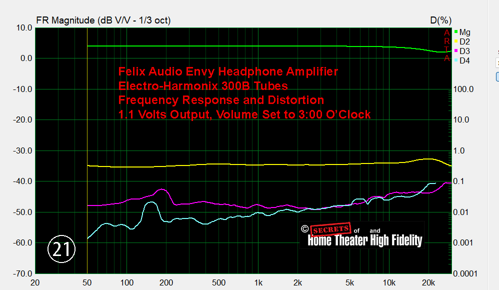
An impulse response-derived frequency response of an amplifier using 300B triodes in a single-ended design is shown below. Notice that the 2nd-harmonic is predominant throughout the audible band (yellow line). The magenta and blue lines are the 3rd-ordered and 4th-ordered harmonics respectively. The 2nd-ordered harmonic is at 0.5% to 0.7%.
Solid-State Amplifiers:
- Clean & Accurate Sound – Solid-state amps reproduce sound with high fidelity, often resulting in a cleaner and more precise output.
- Higher Headroom & Less Distortion – They remain clean at high volumes and don’t introduce as much harmonic coloration unless designed to do so.
- Tighter & More Controlled Bass – Higher damping factors in solid-state amps lead to tighter, punchier low-end response.
- Harsh Clipping When Overdriven – If pushed too hard, solid-state amps can clip abruptly, resulting in odd-order harmonics that sound harsher to the ear.
- More Efficient & Reliable – Solid-state amps are generally more efficient, lighter, and require less maintenance compared to tube amps.
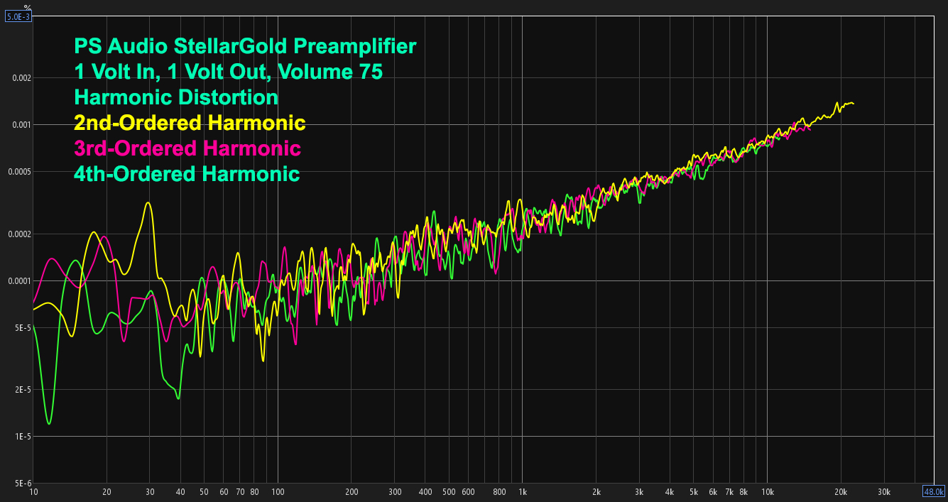
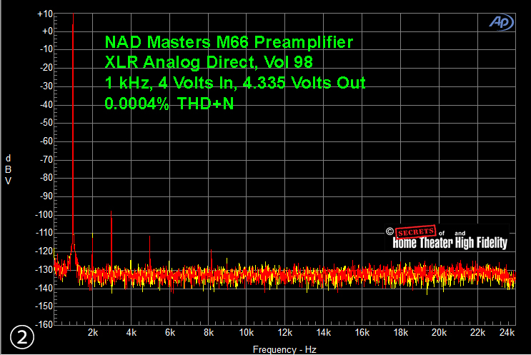
Below is a spectrum from a solid-state preamplifier showing the various harmonics. Note that the 2nd-ordered, 3rd-ordered, and 4th-ordered harmonics are grouped together rather than the 2nd-ordered harmonic standing out from the rest as it did with the tube amplifier shown in the above figure. And, the distortion is well below 0.001%. The second figure below is from a 1 kHz sine wave input to a solid-state power amplifier. Notice that the overall distortion is very, very low, and the 2nd-ordered harmonic is just slightly larger than the 3rd-ordered and 4th-ordered harmonics.
Which One is Better, Tubes or Solid-state?
- For Guitarists – Many prefer tube amps for their organic response and warm overdrive.
- For Audiophiles – Tube amps are favored for their euphonic qualities, but solid-state amps are chosen for transparency and power efficiency.
- For Professional Audio & Home Theaters – Solid-state is often preferred for accurate sound reproduction.
The Different Types of Vacuum Tubes and How They Work
Vacuum tubes come in various types, each designed for specific functions such as amplification, rectification, oscillation, and switching. Below is an explanation of how different types of vacuum tubes work and their respective roles:
- Diode (Two-Electrode Tube)
Function:
- Converts alternating current (AC) into direct current (DC) by allowing current to flow in only one direction.
Structure:
- Two electrodes: a cathode (heated to emit electrons) and an anode (plate).
- Enclosed in a vacuum-sealed glass or metal envelope.
Operation:
-
- The cathode is heated by a filament, causing it to emit electrons (thermionic emission) A negative voltage on the cathode provides a continuous supply of negatively charged electrons.
- When the anode (plate) is positively charged, it attracts the negatively charged emitted electrons, creating a current flow.
- When the anode is negatively charged, no current flows because electrons cannot flow back from the anode to the cathode (the negatively charged cathode repels the negatively charged electrons).
- This one-way current flow is used for rectification in power supplies.
- Here is a diagram of a diode showing thermionic emission from a heated filament © https://www.approachlabs.com/thermionic-emission/:

- Triode (Three-Electrode Tube)
Function:
- Amplifies weak electrical signals by controlling electron flow with a third electrode (the control grid).
Structure:
- Three electrodes: a cathode, a control grid, and an anode (plate).
Some popular (dual) triodes in audio amplifiers include:
- 12AX7 (ECC83) – The most famous dual triode, used in guitar and hi-fi amplifiers. It has high gain (μ ≈ 100) and a warm, harmonically rich tone.
- 12AU7 (ECC82) – A lower-gain (μ ≈ 17) dual triode often used as a phase inverter or buffer in audio circuits.
- 12AT7 (ECC81) – Medium-gain (μ ≈ 60), commonly used in phase inverters, reverb drivers, and preamp stages.
- 6SN7 – A larger, octal-base dual triode with smooth characteristics, often used in high-end hi-fi amplifiers.
- 6DJ8 (ECC88) / 6922 – A low-noise, high-transconductance dual triode, popular in high-fidelity audio and headphone amplifiers.
- ECC99 – Designed for high-fidelity applications, often used as a driver for power tubes.
Phase Inverter and Driver Tubes
- 5687 – A robust, low-microphonic dual triode used for driver stages in high-end audio.
- 6072 (12AY7) – A lower-gain version of the 12AX7, used in vintage microphone preamps and hi-fi circuits.
- 6CG7 / 6FQ7 – Essentially a 9-pin version of the 6SN7, often used in phase inverter and driver stages.
Operation:
- The cathode emits electrons when heated.
- The control grid, placed between the cathode and anode, is biased with a small voltage.
- A positive grid voltage increases electron flow to the anode, amplifying the signal.
- A negative grid voltage reduces electron flow, attenuating the signal.
- The result is an amplified version of the input signal at the output (anode).
- Tetrode (Four-Electrode Tube)
Function:
- Improves upon the triode by reducing issues like capacitance between the anode and control grid, making it more suitable for higher frequencies.
Structure:
- Four electrodes: a cathode, a control grid, a screen grid, and an anode (plate).
Operation:
- The screen grid is placed between the control grid and the anode and is given a constant positive voltage.
- The screen grid reduces the interaction (capacitance) between the anode and control grid, stabilizing operation at high frequencies.
- Amplification works similarly to the triode but with greater efficiency and reduced signal distortion.
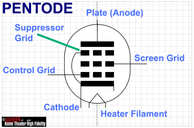
- Pentode (Five-Electrode Tube)
KT-88, KT-120, and KT-150 vacuum tubes are very popular pentodes for power amplifiers, and the wattage output depends on the amplifier’s design, operating voltages, and circuit topology (Class A, Class AB, or push-pull). Here’s a general idea of their output capabilities:
- KT-88
- Single-Ended Class A: ~12-15W
- Push-Pull Class AB: ~50-60W per pair
- Ultra-Linear Mode: ~70W per pair
- KT-120 (a higher-power version of KT-88)
- Single-Ended Class A: ~15-20W
- Push-Pull Class AB: ~60-75W per pair
- Ultra-Linear Mode: ~80-100W per pair
- KT-150 (highest power of the three, designed for maximum dissipation)
- Single-Ended Class A: ~20-25W
- Push-Pull Class AB: ~100-150W per pair
- Ultra-Linear Mode: ~160W per pair
These numbers assume optimal high-voltage conditions (typically 400-600V plate voltage). Some high-end amplifiers push the limits to achieve even greater output.
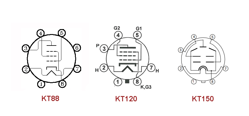
Here is a pinout diagram of the KT-88, KT-120, and KT-150 pentodes in power amplifiers. For the grids, pin 5 is the control grid, pin 4 is the screen grid, and pin 8 is the suppressor grid (as well as the cathode). The second diagram has the various electrodes labeled. Usually the suppressor grid is simply attached to the cathode as in the diagrams, and sometimes it has its own separate connection. The suppressor grid’s function is to repel secondary emission of electrons from the anode, as the anode can get very hot because of the high current that it can conduct during use.
Other popular pentodes for power amplifiers include:
- EL34 – A legendary pentode widely used in hi-fi and guitar amplifiers, known for its warm, dynamic sound.
- EL84 – A lower-power pentode (around 12W per tube) used in vintage and modern hi-fi amplifiers (e.g., Vox AC30 guitar amp).
- 6V6 – Though technically a beam tetrode, it’s often categorized with pentodes and is famous for its sweet, smooth tone.
- 6550 – A high-power pentode (also a beam tetrode) used in powerful hi-fi and bass amplifiers
- 6L6 – While often considered a beam tetrode, it’s widely used in guitar and audio amps.
- EF86 – A low-noise pentode used for preamp stages rather than power amplification.
- ECL82 / ECL86 – Triode-pentode tubes combining both functions, often found in vintage radio and small amps.
Function:
- Further improves upon the tetrode by addressing secondary emission (undesirable electrons flowing backwards from the anode) by adding a “suppressor grid” (see diagram above).
Structure:
- Five electrodes: a cathode, a control grid, a screen grid, a suppressor grid, and an anode (plate).
Operation:
- The suppressor grid is placed between the screen grid and the anode.
- It is usually connected to the cathode (see diagram above) and repels electrons emitted from the anode (secondary emission), preventing them from interfering with the primary electron flow.
- This results in higher efficiency, greater gain, and better performance for audio and radio-frequency amplification.
- Beam Tetrode
Function:
- A specialized tetrode that uses focused electron beams for higher efficiency and power handling.
Structure:
- Similar to a tetrode, but with beam-forming plates to focus electron flow into narrow beams.
Operation:
- Electron beams are directed toward the anode, minimizing the effects of secondary emissions.
- The design increases efficiency, reduces distortion, and improves power output.
- Often used in high-power audio amplifiers and radio transmitters.
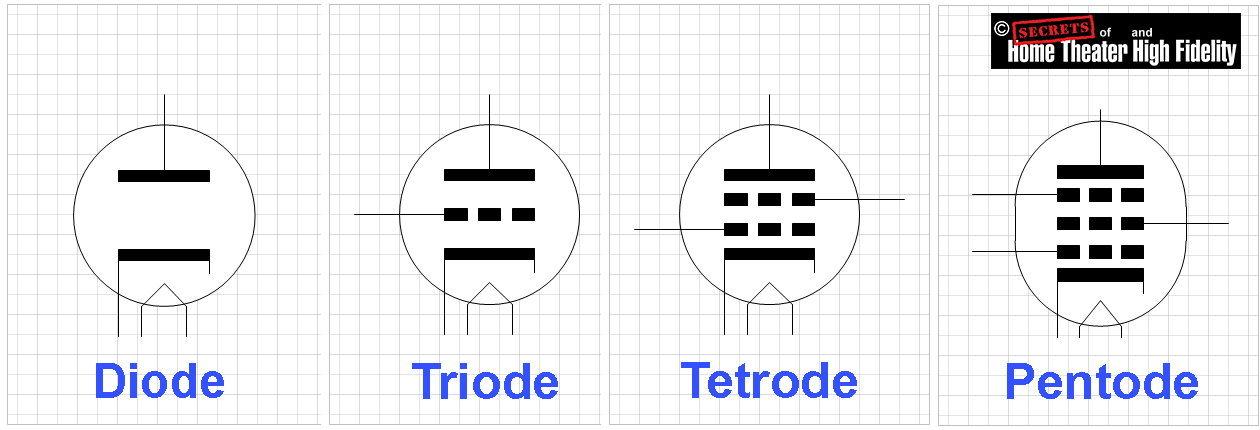
- Here is a diagram of all four main tube types, and where the cathode is heated by a separate filament (called “indirectly heated cathode”).
 The Process of Amplification in a Tube Circuit, using a Triode as an Example: A triode tube amplifies signals by controlling electron flow between the cathode and the plate (anode) using a control grid. Here’s how the process works:
- Electron Emission from the Cathode
- The cathode is heated, either directly or indirectly, causing it to emit electrons via thermionic emission.
- A negative charge develops around the cathode due to the emitted electrons.
- Electron Attraction to the Plate (Anode)
- The plate is held at a high positive voltage relative to the cathode.
- This positive potential attracts the electrons, creating a flow of current from the cathode to the plate.
- Control Grid Modulates Electron Flow
- The grid is placed between the cathode and plate and is negatively biased relative to the cathode.
- A small negative voltage on the grid repels electrons, reducing the current reaching the plate.
- A small positive voltage (less negative) allows more electrons to pass, increasing the current to the plate.
- Because the grid requires only a small voltage change to produce a significant change in plate current, it achieves amplification.
Amplification Process
- A weak AC signal is applied to the grid.
- The small voltage variations on the grid control a much larger current between the cathode and plate.
- The plate current variations create a larger voltage swing across a load resistor in the plate circuit.
- This results in an amplified version of the input signal at the plate.
Thus, the triode functions as an amplifier by using a small input voltage at the grid to control a much larger output at the plate.
- Electron Emission from the Cathode
- Cathode Ray Tube (CRT)
Function:
- Used in older television sets, oscilloscopes, and radar displays to produce images or waveforms on a phosphorescent screen.
Structure:
- A heated cathode emits electrons.
- Control grids focus and control the electron beam.
- Deflection plates or magnetic coils guide the beam to specific points on the screen.
- A phosphor-coated screen emits light when struck by electrons.
Operation:
- Electrons emitted by the cathode are accelerated toward the screen by an anode.
- The beam is deflected horizontally and vertically by electric or magnetic fields to scan the screen.
- The phosphor coating glows at the point of impact, producing a visible image.
- Thyratron
Function:
- A gas-filled tube is used as a switch or relay in high-power circuits.
Structure:
- Similar to a triode but filled with a low-pressure inert gas (e.g., neon, argon, or mercury vapor).
Operation:
- The gas ionizes when a triggering voltage is applied to the control grid.
- Once ionized, the tube conducts a large current between the cathode and anode.
- The conduction continues until the anode voltage drops below a certain level, at which point the tube resets.
- Magnetron
Function:
- Generates high-power microwaves for radar systems, microwave ovens, and communication.
Structure:
- A cylindrical cathode at the center, surrounded by a circular anode with resonant cavities.
- A magnetic field is applied perpendicular to the electron flow.
Operation:
- The cathode emits electrons, which are influenced by the magnetic field.
- The electrons spiral outward toward the anode, interacting with the resonant cavities to generate microwaves.
- The microwaves are extracted and directed for use in radar or cooking applications.
- Klystron
Function:
- Amplifies or generates high-frequency radio waves and microwaves, commonly used in satellite communication and particle accelerators.
Structure:
- Contains an electron gun, resonant cavities, and a collector.
Operation:
- An electron beam passes through resonant cavities.
- The cavities modulate the velocity of the electrons, creating bunches.
- The bunches interact with the output cavity, generating amplified microwaves.
- Phototube
Function:
- Converts light into electrical signals, used in early light meters and optical instruments.
Structure:
- A photosensitive cathode and an anode are enclosed in a vacuum tube.
Operation:
- Light striking the cathode causes it to emit electrons (photoelectric effect).
- The electrons are collected by the anode, producing a current proportional to the light intensity.
These various types of vacuum tubes served as the backbone of early electronics and paved the way for modern solid-state devices like transistors and integrated circuits. Each type was tailored for specific roles, from signal amplification to high-power microwave generation.
The black-and-white TV CRT (cathode ray tube) and the color TV CRT differ in design, complexity, and function because color CRTs must handle the additional challenge of creating multi-colored images. Here’s a breakdown of the key differences:
- Phosphor Coating
- Black-and-White CRT:
- The screen is coated with a single layer of white phosphor that emits light (usually shades of gray) when struck by an electron beam.
- The intensity of the beam determines the brightness of the pixel, producing varying shades of gray.
- Color CRT:
- The screen has three types of phosphor dots (red, green, and blue) arranged in patterns such as dots or stripes.
- These phosphors emit their respective colors when struck by electrons.
- By combining these colors at varying intensities, the tube produces the full range of colors.
- Electron Guns
- Black-and-White CRT:
- Contains a single electron gun that generates one electron beam.
- The beam scans across the phosphor-coated screen to create the image.
- Color CRT:
- Contains three electron guns (one for each primary color: red, green, and blue).
- These guns produce separate beams, which must strike their corresponding phosphor dots precisely to display the correct color.
- Shadow Mask or Aperture Grille
- Black-and-White CRT:
- No need for a shadow mask or aperture grille because there’s only one electron beam and one type of phosphor.
- Color CRT:
- Includes a shadow mask or aperture grille to ensure that each electron beam hits only the correct phosphor (red, green, or blue).
- The shadow mask is a thin metal sheet with tiny holes aligned with the phosphor dots on the screen.
- An aperture grille, used in some designs (e.g., Sony’s Trinitron), consists of vertical wires that align the beams with the phosphors.
- Alignment and Convergence
- Black-and-White CRT:
- The single electron beam does not require complex alignment or convergence.
- Color CRT:
- Requires precise beam convergence, where the three electron beams must meet at exactly the same point on the screen to ensure accurate color reproduction.
- Misalignment can cause color fringes or distortions.
- Deflection System
- Black-and-White CRT:
- Simpler deflection coils (horizontal and vertical) guide the single electron beam across the screen.
- Color CRT:
- More complex deflection system because it must keep all three electron beams properly aligned while scanning across the screen.
- Requires additional magnetic and electrostatic adjustments for precision.
- Power and Complexity
- Black-and-White CRT:
- Simpler circuitry since it handles a single intensity signal (luminance).
- Lower power requirements due to fewer components and simpler phosphors.
- Color CRT:
- More complex circuitry is needed to process the three primary video color signals (red, green, and blue) from the video input.
- Requires higher power to operate the three electron guns and additional components (shadow mask, deflection system).
- Signal Processing
- Black-and-White CRT:
- Processes a single-channel video signal (luminance only), which represents brightness levels.
- Color CRT:
- Processes a more complex signal that includes:
- Luminance (Y): Represents brightness.
- Chrominance (C): Contains the color information (encoded into two sub-signals for hue and saturation).
- These signals are decoded to drive the red, green, and blue electron guns.
- Processes a more complex signal that includes:
- Weight and Size
- Black-and-White CRT:
- Typically lighter and smaller due to fewer internal components and simpler glass construction.
- Color CRT:
- Heavier and bulkier because of the shadow mask/aperture grille, three electron guns, and the thicker screen glass (to prevent implosion and withstand higher stresses from the vacuum).
- Image Quality
- Black-and-White CRT:
- Produces crisp grayscale images without concerns about color alignment or distortions.
- Color CRT:
- Offers full-color images but is more prone to issues such as:
- Color bleeding: When electron beams slightly miss their intended phosphor.
- Convergence errors: Misalignment of the three beams causes color fringing.
- Purity issues: Magnetic interference can cause discoloration in certain areas of the screen.
- Offers full-color images but is more prone to issues such as:
- Applications
- Black-and-White CRT:
- Primarily used in early televisions and monitors, as well as specialized equipment like oscilloscopes and radar screens.
- Color CRT:
- Became standard for consumer TVs and computer monitors in the mid-to-late 20th century.
Summary of Key Differences:
| Feature | Black-and-White CRT | Color CRT |
| Phosphor Coating | Single layer (white/gray) | Red, green, and blue dots or stripes |
| Electron Guns | One | Three (RGB) |
| Shadow Mask | Not needed | Required for color accuracy |
| Convergence | Simple (single beam) | Complex (three beams) |
| Deflection System | Simple | More complex |
| Signal Processing | Single-channel (luminance) | Multi-channel (RGB or YUV) |
| Weight and Size | Lighter, smaller | Heavier, bulkier |
| Image Quality | Grayscale only | Full color |
Secrets Sponsor
These differences highlight the increased complexity of color CRTs compared to black-and-white ones. While black-and-white CRTs were simpler and reliable, color CRTs introduced the vibrant, multi-hued displays that dominated entertainment and computing for decades before the advent of modern flat-panel displays like LCDs, OLEDs, QLEDs, MicroLEDs, and others.
Vacuum tubes (valves) play an important role in the history of electronics, including audio and video. With more than 100 years of continued development, they remain a significant part of the world of the audiophile.
Other Technical Articles of Interest:
Audio Capacitors: Their Purpose, How They Work, How They Are Manufactured, and How They Affect the Sound – John E. Johnson, Jr.
An Audiophile’s Guide to Quantization Error, Dithering, and Noise Shaping in Digital Audio – John E. Johnson, Jr.
The Design and Function of Transistors in Audio: Past, Present, and Future – Robert Cordell
Life on the Edge – A Personal Perspective on the Past, Present, and Future of Class D Audio Amplifiers – Bruno Putzeys
Raising the Bar on Speaker Performance. A Loudspeaker Designer’s Perspective – Bill Dudleston
The Sound of Tubes – Why is it So Good? – Lukasz Feliks
https://hometheaterhifi.com/30th-anniversary/the-now/the-sound-of-tubes-why-is-it-so-good/
REFERENCES
Books
- “The Valve Amplifier” by Morgan Jones
- “Radiotron Designer’s Handbook” by F. Langford-Smith
- “Principles of Electron Tubes” by Herbert J. Reich
- “Vacuum Tube Amplifiers” by K. R. Sturley
- “History of Electron Tubes” by S. Ando
- “Television Engineering Handbook” by K. Blair Benson
- “Basic Television and Video Systems” by Bernard Grob and Charles Herndon
Research Papers and Journals
- “The Origins and Early Development of Vacuum Tubes”, IEEE History Proceedings
- “A Study on Thermionic Emission in Vacuum Tubes” (Journal of Applied Physics)
- “Color CRT Technology: Shadow Mask and Aperture Grille Advances” (Journal of Display Technology)
- “Comparison of CRT and LCD Displays” (Society for Information Display)
Online Resources and Websites
- National Valve Museum
- http://www.r-type.org/
- A comprehensive database of vacuum tubes, their types, and specifications.
- All About Circuits
- https://www.allaboutcircuits.com/
- Tutorials on how vacuum tubes work, including diagrams and explanations for various types.
- Vacuum Tube Valley
- http://www.vacuumtube.com/
- A site dedicated to vintage vacuum tubes, with information on their history, usage, and restoration.
- The Valve Museum
- https://valvemuseum.org/
- Focuses on rare and historical vacuum tubes.
- Antique Radio Forums
- https://antiqueradios.com/
- A community of enthusiasts discussing vintage radio technology, including vacuum tubes and CRTs.
Technical Manuals and Datasheets
- RCA Receiving Tube Manual (RC-30)
- One of the definitive references for vacuum tube specifications and applications.
- General Electric Essential Characteristics of Tubes
- Provides detailed information on tube types, characteristics, and usage.
- Television Service Manuals (Vintage)
- Many service manuals for black-and-white and color CRT TVs (e.g., RCA, Zenith, and Sony models) include detailed schematics and explanations of CRT operation.
- Mullard Technical Handbook
- Covers design, operation, and testing of various vacuum tubes, including CRTs.
Videos and Documentaries
- YouTube Channels on Vacuum Tubes:
- Mr. Carlson’s Lab
- A deep dive into vintage electronics and tube amplifiers.
- https://www.youtube.com/user/MrCarlsonsLab
- Uncle Doug
- Focuses on vacuum tube amplifiers and electronics repair.
- https://www.youtube.com/channel/UCuqvYOx4H59D9vLeBlLq6nQ
- The 8-Bit Guy
- Explores retro technology, including CRTs and vacuum tubes.
- https://www.youtube.com/user/adric22
- Mr. Carlson’s Lab
- Documentaries:
- “The Secret Life of Machines – The Television”
- Explains how black-and-white and color TVs work in an engaging way.
- “Tube Magic: The History of the Vacuum Tube”
- A detailed documentary about the development of vacuum tubes and their impact.
- “The Secret Life of Machines – The Television”
Specialized Articles
- How Vacuum Tubes Work (ExplainThatStuff.com)
- https://www.explainthatstuff.com/how-vacuum-tubes-work.html
- A beginner-friendly explanation of vacuum tube functionality.
- The Differences Between Black-and-White and Color CRTs (TechHistory.com)
- A detailed article explaining the design and functional differences.
- How Tubes Work, Rob Robinette, https://robrobinette.com/How_Tubes_Work.htm
- CRTs: How They Work and Why They Were Replaced (Display Technology Blog)
- A technical yet accessible overview of CRT operation.
Forums and Communities
- DIY Audio Forum, https://www.diyaudio.com/
- Vintage Radio and Phonograph Society, https://vrps.org/