

Introduction
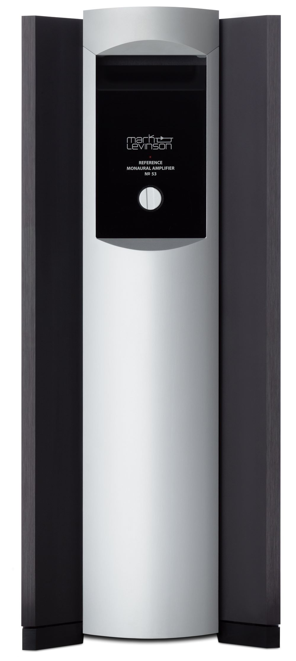
Mark Levinson is a state-of-the-art brand, whose products are purchased by consumers whose bank accounts are also state-of-the-art. Levinson makes no apologies for their prices, nor do they have to justify them. The axiom is simple: If you want the best, it costs a lot. The latest addition to their power amplifier line takes a huge leap from the previous designs, which were Class AB, and which usually were biased well into Class A operation. The Mark Levinson No 53 is a monoblock power amplifier that is a switching design, i.e., the output stage is operated in switching mode, but it is unique in that it interleaves eight switchers (Levinson calls it Interleaved Power Technology, or IPT) to produce a fully balanced output, at a realized switching frequency of 4 MHz.
It weighs 135 pounds, which, at first, surprises those of us who are familiar with switching amplifiers. They usually are very light weight, due to their efficiency.
Specifications
- Design: Solid State Monoblock Power Amplifier; Switching Output Stage
- Power: 500 Watts RMS into 8 Ohms, 1,000 Watts into 4 Ohms
- MFR: 10 Hz – 20 kHz, ± 0.1 dB
- THD+N: Not Specified
- S/N: 85 dB (@ 1 Watt into 8 Ohms)
- Inputs: XLR and RCA
- Input Impedance: 100 kOhms Balanced (XLR), 50 kOhms Unbalanced (RCA)
- Outputs: Two Sets of Speaker Binding Posts for Bare Wire or Spade Lugs
- Other Connections: Ethernet, Link Port (connection to othe Levinson products), Trigger
- Dimensions: 20.4″ H x 8.4″ W x 20.4″ D
- Weight: 135 Pounds
- MSRP: $50,000/pair USA
- Mark Levinson
The reason the No 53 weighs so much is that it uses a conventional power supply. The switching occurs only in the output stage. The power transformer is a 2.8 kVa toroid, and there are 188,000 µF of power supply capacitance. There is an additional 106,500 µF of local capacitance for circuits other than the rail voltage.
The amplifier is rated at 500 watts RMS continuous output into 8 ohms and 1,000 watts into 4 ohms. It is capable of delivering short transient power levels much higher than the rated output.
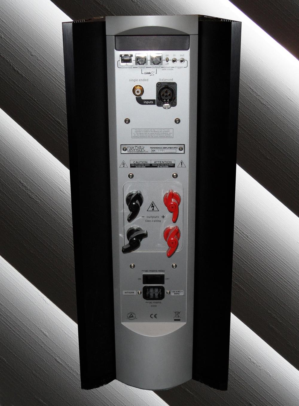
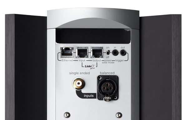
The rear panel has the inputs near the top, both RCA and XLR, plus an Ethernet port for communicating with other Levinson equipment in your home network, a port for direct hard wire communication with other Levinson products, and a trigger. There are two sets of speaker binding posts that accept bare wire or spade lugs. The hole that would otherwise accept banana plugs is blocked with a plastic insert. The on/off toggle switch is at the bottom, and you can put the amplifier in two states. One is that the power button on the front panel switches the amplifier from a cold start off, or from a warm standby, selectable with a switch on the top of the rear panel.
A close-up of the networking jacks is shown below.
The Design
The No 53 has four amplifiers (called amplifier blocks) that have a very unusual configuration. Each amplifier block pair has two “switches” in the output stage that consist of two MOSFET transistors per switch, connected in parallel. So, there are a total of eight switches (sixteen transistors) to produce the output signal.
As to the No 53’s overall design, there are four sub-sections: the power supply, the analog input stage (balanced and unbalanced), the modulation section, and the amplifier output stage. The power supply was described in the preceding section (Page 2), and has a 2.8 kVA toroidal transformer and 188,000 µF of capacitance. The input stage is fully balanced, and if you use the RCA unbalanced input jack, the signal is converted to balanced and remains so throughout the amplifier circuit. The modulation section is where the interleaving circuit is located. It has four isolated modulator sections, one each to modulate the four amplifier blocks.
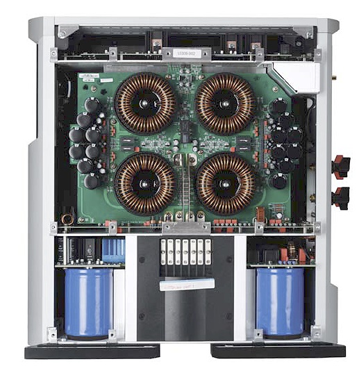
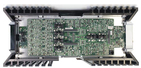
Below is a photo of the inside of the No 53, with the amplifier boards removed, to show huge inductors, the local power supply capacitors on either side of the inductors, and the main power supply capacitors at the bottom. The second photo shows the modulator PCB, which has more than 1,500 parts.
In the Levinson No 53, each amplifier block operates with each switch (two output MOSFET transistors) delivering the entire waveform, both positive and negative portions. Each switch is turned on and off 500,000 times per second, but they are “interleaved” so that they are not switched on at exactly the same instant.
Summarizing the activities of each of the two switchers in each of the four amplifier blocks, here is what happens: For amplifier block 1, switch 1 comes on at 00 going positive, and switch 2 comes on at 1800, going negative. Then in amplifier block 2, switch 1 comes on at 450 going positive and switch 2 comes on at 2250 going negative. For amplifier block 3 we still get the phase shift but the direction of the voltages is reversed, so switch 1 comes on at 900 going negative, and switch 2 comes on at 2700 going positive. For amplifier block 4, switch 1 comes on at 1350 going negative and switch 2 comes on at 3150 going positive. The interleaving process results in an effective switching frequency of 4 MHz.
Those large inductors in the photo shown above, allow the switches to be on at the same time. This is very important, because in conventional switching amplifiers, the output devices (there are usually a total of two output devices in the amplifier) are never allowed to be on at the same time because this would produce “shoot-through” current that would cause the amplifier to fail. Making sure that the two output devices are never on at the same time results in “deadtime” which causes distortion. Manufacturers try to keep the deadtime as short as possible, but it is never 0, so there is always some deadtime, with resulting distortion.
At the crossover point (where the waveform goes from positive to negative, or negative to positive), the switches in all four amplifier blocks are on at 50%, which results in a net current flow of 0. However, the fact that they are on, results in no crossover distortion.
Two amplifier blocks are arranged in parallel, and deliver the output in phase with the input. The other two amplifier blocks are also in parallel, but operate out of phase with the input through the use of a phase inverter at the input stage, and their output is, therefore, out of phase. The in phase output is connected to the + speaker binding post (red), while the out of phase output is connected to the – speaker binding post (black). This results in a fully balanced output.
Shown below is a block diagram of a conventional Class D switching amplifier output stage vs. the Levinson with its IPT circuitry. The presence of the inductors separating the two diodes is what allows the switchers to be on at the same time. You can see how large those inductors are in the first photo above, of the inside of the chassis.
Here is a spectrum from a switching amplifier that uses two output devices, switched at 500 kHz. There is no interleaving involved. This is the spectrum before filtering.
Compare that spectrum with the spectrum from a No 53, shown below (spectra © Harman International), also before filtering.
In Use
OK, enough of the graph stuff. Let’s listen to some music. I tested the two No 53’s with a McIntosh MCD500 SACD player, Balanced Audio Technology VK-5i preamplifier (connected to the No 53’s via XLR cables), and Carver Mark IV ribbon speakers. Cables were Legenburg, Emotiva, and Marc Audio.
The following CD (also available as 50 kHz SACD) is what I always use to see what an amplifier is capable of. Well, the Levinson No 53 is quite capable to say the least. The introductory bass drum notes in “Fanfare for the Common Man” are thunderous and difficult to reproduce, but the Levinson did not flinch in the slightest. The brass were bright but appropriately so, not harsh. The crack of the whip in “Rodeo” was as sharp and snappy as I have ever heard it. I cranked up the volume with this disc, and it matched my reference amplifiers, McIntosh MC1201 monoblocks, during transient demands that indicated 1,000 watts output on the McIntosh meter (I used the No 53 for one channel and the MC1201 for the other). The nominal impedance of the speakers (Carver Mark IV ribbon) is 6-8 ohms. So, while the McIntosh MC1201 can deliver 1,000 watts into 8 ohms continuously, the No 53 can also deliver 1,000 watts into 8 ohms during short transients, which is realistically the only time you would really need that much power. This relates to the huge power supply that the No 53 has.

One of my favorite tracks from this Telarc SACD is “The Great Gate of Kiev”. The strings span several octaves, and were crystal clear, without any sign of metallic edginess.

This Telarc SACD of Vivaldi and Bach Baroque music has period instruments and a quartet of voices from soprano to baritone. Although it is not the style of music that you would crank the volume, all of the instruments’ delicate harmonics seemed to be present, with no addition from switching frequency artifacts.

This gargantuan composition from Handel has more than 50 individual tracks, but in keeping with the season, I pulled it out and listened to both discs (Linn Records). Perhaps the last track is the most familiar, but the entire composition is a stunning masterpiece, and I played it on a stunning masterpiece. The sound would have pleased Handel, I am certain. The clarity that kept the midrange from being congested was simply amazing. In the high frequencies, detail from the No 53’s was slightly better than with my reference MC1201’s.

My general feelings about the No 53 is that it reminds me of Pure Class A sound, and that is something I never thought I would experience with a switching amplifier. Velvety smooth with a satin sheen. The No 53 represents engineering brilliance, no question about it. This amplifier is not only revolutionary, it is a revelation in sound quality.
On the Bench
As with some of my previous reviews, I used one of my Carver speakers as the load for some of the tests.
With a 1 kHz sine wave and 10 volts into the Carver speaker, THD+N was a very, very low 0.002%. The second harmonic is the largest one, which is a good thing.
IMD was 0.02%, again, into the Carver speaker.
Using a combination of 19 kHz and 20 kHz sine waves, the B-A (20 kHz minus 19 kHz) peak at 1 kHz was 100 dB below the fundamentals.
THD+N vs. Frequency into the Carver speaker yielded a curve where the distortion peaks at 8 kHz.
Here is an impedance/phase plot for the Carver speaker. Notice that the region between 3 kHz and 8 kHz has low impedance coupled with 650 phase, which is the most difficult area of the speaker’s impedance to handle. That is why the distortion in the curve shown above peaks in the same region.
The measured frequency response was 20 Hz to 50 kHz, – 0.3 dB.
Power output into an 8 ohm load showed the sharp knee at 500 watts, with clipping (1% THD+N) at 600 watts.
At 4 ohms, the hard knee was at 800 watts, with clipping at 900 watts. However, there was so much voltage drop out of the AC socket (about 108 volts instead of 120), I am sure this low voltage supply was the reason. I have no doubt this amplifier will deliver full spec output. It is getting to the point that today’s amplifiers are so powerful, we may need to install voltage regulators as an integral part of our home theater systems.
Conclusions
The Mark Levinson No 53 power amplifier is a very unusual, very innovative design. It’s switching taken to a much higher level of performance. The sound, however, is not unusual, that is, not unusual for Mark Levinson. This is one hell of a product.