

I was asked to contribute this piece because supposedly there’s an amplifier revolution in the air. I thought that was old news. Bear with me as I dial down the fever pitch somewhat; the reality is much more rewarding.
When in the late nineties and early noughties the class D race got going in earnest, a wondrous array of contrivances gathered at the starting line. Some were half-bridge, some full bridge, controlled in tandem or separately. Some generated PWM straight from a digital input signal, others had analog inputs. Some had no error control, some took feedback at the switching stage, and a few mixed in some feedback from the speaker terminal. Quite a few justified their design choices by quoting from various bits of audio mythology. Probably the most extreme case had 16 power FETs and 7 inductors per channel, with fancy counter logic to demultiplex a DSD stream over all those output switches, netting at once the “direct DSD”, “power DAC” and “zero feedback” prizes.
It was a time for trying out new things. It was wild.
Most of those ideas were nonstarters, their touted advantages undone by supposedly second-order problems that were in fact fundamental. Only a few precipitated out that were genuinely useful and amenable to refinement.
Our little tour around class D will necessarily be provincial. You’re an audiophile or A/V enthusiast. I’m an audiophile designing high-performance power modules for the Hi-Fi, studio, and A/V markets. So that’s what I’ll be writing about, not about amplifiers for phones, hearing aids, or boomboxes. Those generally suffice with such rudimentary amplifiers we needn’t bother with them.
Class D amplifiers were first described in Burnice Bedford’s patent (US1874159), filed in 1930. It shows a pair of triodes acting both as power switches and comparators, driven by the sum of a triangle wave and an audio signal.

There’s every sign that he built it: he draws in details like overshoot on the PWM signal and the switching residual on the filtered waveform, things the armchair inventor wouldn’t think of.
Class D amplifiers explicitly intended to drive loudspeakers started appearing in the late 60’s. Notable names from that period are Brian Attwood and John Ulrich, whose work appears among others under the Peavey and Spectron brands, respectively.
The topology pioneered by Bedford cemented the parts you’ll find in the block diagram that all pop-sci articles about class D amplifiers start off with:

The audio signal (thin blue line) is compared with a high-frequency triangle wave (grey). The comparator puts out a square wave (red) whose “high” and “low” times are dictated by the ratio between the audio voltage and the peak/peak voltage of the triangle wave. The power stage reproduces this same signal with “high” being the positive supply voltage and “low” being the negative (purple). Passing that signal through an LC filter leaves only the average (thick blue line), which is the audio signal.
When the input signal hits the crests of the triangle wave, the comparator produces a signal that’s solidly high and the amplifier’s output voltage equals the positive supply rail. Mutatis mutandis for the negative maximum. Thus, gain works out as the power supply voltage divided by the peak/peak amplitude of the triangle wave.
This is the canonical class D amplifier, the schoolbook topology.
This was unfortunate. Being splendidly easy to understand, it led generations of designers to believe that it was the fundamental class D amplifier and the best starting point for future development. Neither was true. It suggested that the modulator, power stage, and output filter were independent elements, to be designed and optimized separately.
The designation “class D” didn’t help either. Previously known amplifier classes were, A, B,1 and C, so D was the next in the alphabet. Sadly, that letter, combined with the binary nature of the output stage, convinced even intelligent people that it stood for “digital”. You’d think that a device that delivers a time-varying voltage and current into a loudspeaker load is unambiguously analog, but enthusiasm often precludes clear thought. Still today, the German technical lexicon does not have a word for “class D”. They call it Digitalverstärker, as do the Japanese (dijitaru ampu). I tried to launch the word Impulsserienverstärker but despite its satisfyingly Germanic length the term never stuck.
So, in the case of the modulator, it seemed logical to build a digital counter circuit to turn PCM directly into PWM and use it to put together a “power DAC”. The idea certainly has a high PowerPoint appeal: even product managers could see how it was supposed to work.
PCM to PWM conversion is harder than it sounds because it entails converting the audio, which is sampled at perfectly regular intervals, into PWM whose actual sampling times are the switching edges themselves, which depend on the signal. That made it a delicious academic challenge and for over ten years, AES conventions hosted paper after paper describing ever more complex algorithms with gradually improving linearity.
After a while, even the most generous observer couldn’t help suspecting that the various authors were trying hard to put off the real problems, which are the power stage and the output filter2.
While the power transistors are rapidly switched on and off, there is no way to do so infinitely fast. One turns gradually off while the other gradually comes on, and in this interval the output impedance is high. The true moment when the output flips, becomes dependent on the speaker current.
 and time (ns)")
A positive current causes the rising edge to slow down and the falling edge to speed up. Vice versa for negative currents.
You might think that the 40 ns error band we see on the scope picture isn’t a lot. I’d agree that this particular power stage is no slouch, but you must see this relative to the length of one complete PWM cycle. If your amp runs at 500kHz, 40 ns represents over a percent which, if left untreated, directly translates into a similar distortion figure.
Timing error is the easiest-understood source of distortion in class D, which is why particularly first-timers make it the exclusive focus of their attention. Because what else is there? Oh dear!
Recall that given an independently generated PWM signal, the output voltage is directly proportional to the supply voltage. The supply voltage affects the output, not just at clip, but all the time. Any ripple in the power supply ends up amplitude-modulating the audio signal.
Thus, for an amplifier using pure digital PWM (or “schoolbook” analog PWM for that matter), the only countermeasure is to tightly regulate the supply rail.
You’d like to think of a filter as having e.g., a Butterworth characteristic or some such. But in a passive filter, the response depends entirely on the load. As an example, here is a set of curves for the same filter with 4-ohm (red), 2-ohm (green), and 8-ohm (magenta) loads, and the blue trace is a simulated loudspeaker load.

You will appreciate this kind of error is not something that recommends an amplifier for Hi-Fi.
You could make the problem ten times smaller by increasing the corner frequency tenfold, but you’d have to increase the switching frequency by a factor of ten as well. And that increases distortion, per the above. There is literally no satisfactory way to make the frequency response load-independent by just twiddling with the design parameters of a schoolbook amplifier.
Secrets Sponsor
Practical output inductors use magnetic cores to reduce resistance and prevent stray magnetic fields. All magnetic materials have so-called hysteresis, which in turn causes distortion. What makes hysteresis so insidious is that with a sinewave input, it’s almost invisible. Put two sinewaves together though and they will interact in a most convoluted manner.
Commentators regularly and confidently confuse hysteresis with saturation. An important difference between the two is that saturation only shows up with large signals. Hysteresis distortion by contrast is almost constant, in percentage terms, relative to the signal level. Left untreated it’s constantly hovering at the edge of audibility, a subtle gritty haze over the soundstage. When you hear people complain about the sound of older class D amplifiers, this is generally the cause. It would take us rather far to delve into it here, but a rather spectacular demo can be found here3.
Fortunately, there’s one remedy that is fantastically effective at removing hysteresis distortion, stabilizing the output impedance, eliminating switch time distortion, and negating the dependency on the power supply voltage, all at once. We’ll go into this exciting technology in a bit.
Straight digital switchers do have their uses. Many products only require modest performance, such as boomboxes, soundbars, and the like. Converting PCM to PWM and directly boosting that with a pair of FETs is by far the cheapest way to drive a speaker, so long as you don’t expect Hi-Fi.
Looking back to the 90’s when serious audio researchers were still pouring their energy into digital PWM modulators expecting audio nirvana, only one high-end project materialised. It was called the TacT (latterly Lyngdorf) Millennium.
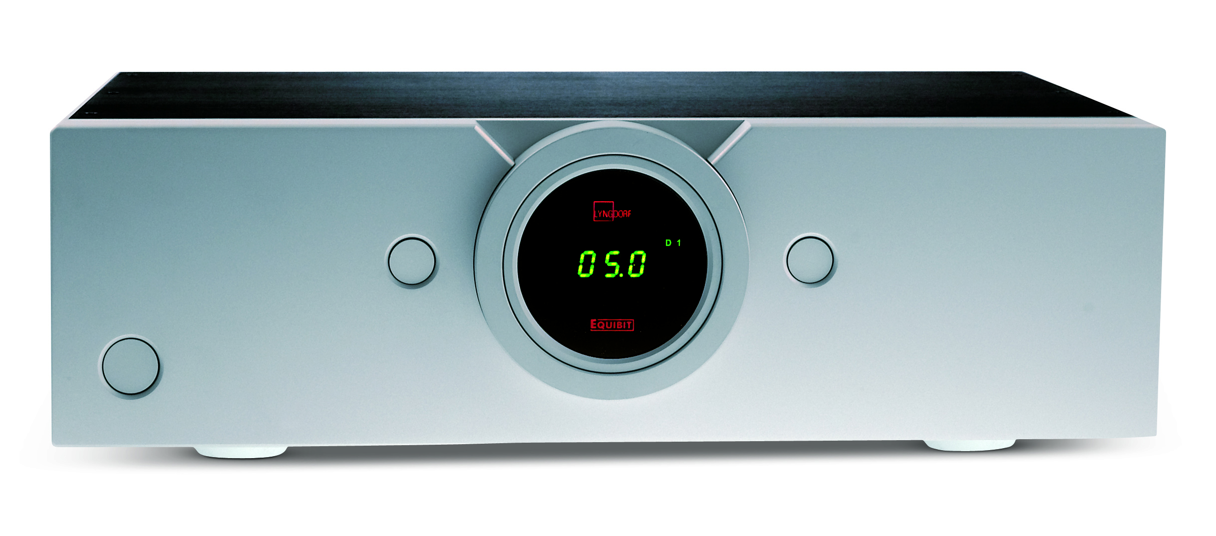
The power stage was fast, very, very fast. This was done by beefing up the gate drivers to deliver up to 12 amperes. The power supply was very stiffly regulated and made a virtue of the amplitude modulating effect by using the supply voltage as volume control. The output inductor was air-cored because it was the only way of getting rid of hysteresis distortion. The frequency response problem was not addressed at all, with some users commenting that compatibility with different speakers could be hit-and-miss. It is very much a “power DAC” (the very first) but I should be wary of characterizing it as a “digital amplifier” because all that effort with the power supply, gate drivers, and output filter are, from the first to the last, analog engineering done to get around very analog distortion sources. It is still the highest-performance open-loop (i.e. zero-feedback) amplifier ever manufactured. More recently the appearance of GaN FETs has inspired novice designers to re-run history and reinvent this kind of amplifier, but I’ve yet to see one that comes close.
Having said all that, the Millennium’s performance is only impressive considering that it was open-loop. Otherwise, 0.03% THD is hardly state-of-the-art. Much as it was a tour de force, I can only describe it as a terrible idea, brilliantly executed.
(The designer, Lars Risbo, is now my friend, colleague, and partner in Purifi, where he is head of transducer research. I dearly hope he isn’t reading this.)
When you go to a Hi-Fi show, you can’t throw a brick without hitting someone who believes that vinyl is superior to digital. The reason is simple. There was a time in the early 80’s when an early 80’s CD player playing an early 80’s CD was a bit of a letdown compared to the corresponding vinyl. For some, the experience must have been positively traumatizing because 40 years later they still believe it’s true.
By the same expedient you can quickly locate someone ready to provide a blanket statement to the effect that “negative feedback is bad for sound”. A similar history underlies this. Prior to solid-state, nobody batted an eyelid at amplifiers using feedback. Early transistor amplifiers had something of an Achilles’ heel though, which was distortion in the differential input stage. Ironically, the paper that popularised the concept of “TIM” (transient intermodulation) distortion correctly identified the root cause, but nobody read that far4. Instead, the distortion was blamed on the use of negative feedback.
The irony is this: firstly, the diff amp is not in fact inside the feedback loop. It’s trivially easy to linearise the input stage and eliminate TIM without changing the amount of feedback. Secondly, if you increase the gain of the amplifier prior to feedback, the signal on the diff amp becomes correspondingly smaller, thus preventing the distortion from arising in the first place. You read that right: more loop gain (i.e. more feedback), less TIM. But since understanding this requires a modicum of curiosity, there will always be those who won’t recognize a plain fact if it danced the conga naked in front of them.
I, for one, always keep a handy supply of bricks at Hi-Fi shows.
Nowadays seasoned class D designers are unbothered by such compunctions. It works, it makes amplifiers sound fantastic. If knowing that an amp uses feedback causes conniptions in some circles, that’s not something we have a technical solution to.
But that is now. Having got wind of my snarky characterization of the Millennium, Lars looked me in the eye and said “Mate, it was the nineties. Did you know how to put feedback around a class D amp back then?” That was me being told.
The question wasn’t so much whether feedback was a good idea or not, but whether it could be made to work at all.
While not exactly a law of nature, it’s generally true that when you take an amplifier that works somewhat acceptably without feedback, adding feedback afterward is not straightforward. There’s no end of tales from people trying to compare the sound of an amplifier “with or without feedback” and being disappointed5. That is if the experiment isn’t stymied by stability problems right away. Conversely, an amplifier designed with feedback in mind will simply stop working when you open the loop.
This puts the lie to the myth that adding feedback is a cop-out, an easy fix. The truth is that unless you set it up as a feedback amplifier from the get-go, you’re likely to be stuck with a lumbering beast that’s very hard to control. As luck would have it, the schoolbook class D amplifier is a case in point.
The first problem was that the feedback signal wasn’t clean audio but necessarily contained a residual from the PWM process. Adding that back into the modulator caused more distortion than it cured. It took years before practical solutions materialized.
The second problem is worse: since the output filter is the most intractable part, we’d like to include it inside the feedback loop, Thank you very much! Sadly, that same variable phase shift is now free to wreak havoc on the stability of the loop. It turns out that if you have a modulator with a “clock” (what we call the triangle wave that sets the switching frequency), you can’t really do a loop with a lot of gain that is stable across a full range of load impedances. You’d need a controller that can auto-adjust its loop filter when a different load is connected6.
I’ve already hinted that the clocked (schoolbook) class D amplifier isn’t even the simplest topology. This one is:
 class D amplifier simple topology diagram")
There is no oscillator. The combined effect of the feedback network, the output filter, and the delay through the comparator and the power stage cause the circuit to self-oscillate at a convenient frequency. There’s no separate modulator either. Adding a signal to the input simply shifts the frequency and duty cycle to a different stable point. Gain is independent of the supply voltage because the oscillation’s amplitude itself is set by the supply voltage, thus removing the supply voltage from the equation. The feedback is global and has a substantial loop gain, easily 30dB or more, so this circuit distorts 30 times less than a schoolbook amplifier with the same power stage. The output impedance is very low, and the frequency response is load-independent to such an extent that the corner frequency is completely erased from the response plot. More maddeningly still, it’s the output filter itself that supplies this loop gain, not the feedback network.
This plot is from a basic prototype from 2001, shown here with loads of 2-ohm (red), 4-ohm (green), and open circuit (blue). Even in the open circuit case, there is no trace of the physical resonance of the LC filter (35kHz).
, 4-ohm (green), and open circuit (blue) lines of a class D amplifier measured by dB and Hz")
I chose this plot because in more recent exemplars you can’t distinguish the three curves at all.
I’m often credited with this invention which I called “Universal class D” (UcD), and was in fact granted a patent for it (US7113038B2). Its sheer simplicity annoyed the hell out of everyone else who had, until then, used much more complicated designs that didn’t work half as well. So, to help liberate the IP, a gallant competitor generously spent time on Google Patents and ferreted out a lapsed patent from 1977 by one Clayton Sturgeon (US4041411), which describes a similar arrangement!
Consider: in an ideal world, Sturgeon would be famous as the inventor of this fundamental circuit. Instead, it was completely forgotten. What a missed opportunity for the audio industry. Sturgeon’s invention should have wiped the Rube Goldberg contraption that is the schoolbook amplifier from our collective memories there and then. The amplifier technology shift that’s happening today could have been over and done with by 2000. Admittedly I’ve made a lovely career out of perfecting class D, but really, I’m sure I’d have found something else to do.
Other self-oscillating amplifiers were in the running too, but those actively avoided involving the output filter in the oscillation, instead using pre-filter feedback to set the frequency and keeping post-filter feedback (if any) to a minimum. Sturgeon’s stroke of genius (and belatedly, mine) was to add phase lead to the feedback network so that even with the entire second-order LC filter in the loop you could freely set the oscillation frequency and completely control the output filter on top of that.
Even in this embryonic form, the circuit performs well enough for most uses except serious high-end audio.
Secrets Sponsor
Self-oscillating amplifiers have this almost magical property that they achieve much higher loop gain than a clocked amplifier with a loop filter of the same order. This remains true if you use full global feedback. In fact, it automatically finds a new stable optimum when you change the load, without further intervention.
For the longest time, this was no more than a practical observation, but it’s been put on a solid mathematical footing since7. I’ll spare you the details but what that means is this: it is now a proven fact and not an opinion that self-oscillating amplifiers are inherently more stable, and inherently allow more loop gain, than clocked amplifiers.
Not that anyone was waiting until the jury was in. Finding mathematical proof merely vindicated designers who’d already pitched their collective tents there. After all, it was plain enough on the lab bench. Carsten Nielsen, former CEO of ICEpower, enjoyed explaining how his Ph.D. student Niels Anderskouv one day forgot to turn on the triangle wave on an amplifier he was working on. As if by magic, performance improved. This gave the impetus for the company’s first line of amplifier modules called COM (Controlled Oscillation Modulation). Their current offering is based on a global loop and is, with characteristic poetry, called GCOM.
We owe a debt of gratitude to the enterprising sleuth who set out to undercut the novelty of the UcD patent and decided to publicize his find. With the circuit known by all to be public domain, nobody needed to invent excuses for having to use clumsy alternatives. That the global-loop self-oscillating amplifier is the simplest, most fundamental class D circuit has become an uncontroversial fact of life, one that everyone is comfortable with.
You can understand my bemusement at being asked to provide commentary on what’s supposed to be an amplifier revolution happening right now. To me, the revolution was over when the entire competing peloton settled on self-oscillating amplifiers with global feedback.
What followed was merely consolidation and refinement. That it looks otherwise to many audiophiles is because in practice, these “refinements” broke one performance barrier after the other. Every generation posted 10 times lower distortion than the one before. In my case, the iterations were called UcD (2000), Ncore (2008), and Eigentakt (2016). I ran out of inspiration, so the next one is still called Eigentakt.
In circuit terms, those innovations took the form of (various, patentable) ways to add further gain to the feedback loop without affecting the large signal behavior of the amplifiers. In design terms, they were advances in the mathematics underlying self-oscillation which has only become complete in recent years, and which permits computer optimization of circuit parameters without having to resort to a full-blown simulation or worse, experiments.
Every time I and afterward my competitors made such strides, class D amplifiers got accepted into ever higher strata of the Hi-Fi market. Not because of how they measured, but because of how they sounded. Barring a few geeks and cranks, nobody buys an amplifier based on measurements alone. People listen and only shell out if they enjoy what they hear. This belies the received wisdom that improved measurements are irrelevant, particularly where feedback is involved.
There’s an irony here. Many audiophiles still think that anti-measurement and anti-feedback sentiments are somehow countercultural and refreshing. They’re not. They’ve been the established culture for over 50 years, perpetuated by self-proclaimed engineers with more charisma than math chops who’ve been taking you for a ride.
A typical design cycle in esoteric high-end circles consists of taking a product one really likes the sound of and calling that the “reference”. Then, more or less randomly, bits and pieces of a new prototype are tweaked until it sounds “better” than the reference. The prototype goes into production and becomes the new reference.
This Brownian motion of sonic ideals and outcomes explains how some “Hi-Fi” components can sound so utterly unalike. This practice of “designing by ear” attempts to short-circuit the most powerful design resource we have at our disposal, which is the bit that sits between those ears. Sound quality is not a mystery. It’s a tractable problem if only we care to think it though.
Let me suggest that if we’re building an amplifier, the reference is simply the signal that goes in. The better amplifier is the one whose output signal is the hardest to distinguish, by ear, from the input signal. The intelligent way forward becomes to construct listening tests expressly aimed at learning what is audible and what is inaudible. And if audible, what is objectionable and what is benign? Once you have this knowledge, you can reuse it forever to inform your technical choices. This is what I like to call “design for ears”.
The aim of negative feedback is to render an amplifier inaudible. It works on easily measurable distortion mechanisms as well as badly understood ones. For example, it removes the sonic signatures that some passive components impart on a circuit. No more qualifying parts by ear. We don’t even need to know why a particular capacitor has a particular “sound” because, wrapped in 80dB of feedback, it won’t. Where listening comes in is that you still need to decide on the precise parameters of your feedback system, and you can’t do that in a vacuum. Least of all with a class D amp.
In a linear (i.e. class A, AB, or B) amplifier, bandwidth and speed are easily achievable. As a result, the default way to improve distortion is to increase bandwidth. With standard “dominant pole compensation”, loop gain follows proportionally. So-called two-pole compensation is considered highly advanced.
Consequently, there’s nothing in a linear amplifier that explicitly marks it out for audio. High- frequency parameters like slew rate or THD at 20kHz correlate reasonably well with subjective sound quality for the simple reason that they correlate with bandwidth.
Sadly, tons of bandwidth is the one luxury the designer of switching amplifiers doesn’t have. PWM is a sampling process. As in digital audio, the sampling rate directly sets the bandwidth of the system. But you can’t just increase the switching frequency willy-nilly because that increases power losses and lowers headroom. New semiconductor technologies notwithstanding, sensibly designed class D amplifiers are unlikely to have more than a six-digit bandwidth for the foreseeable future.
The consequence is that the strategies deployed in class D are more akin to sigma-delta AD/DA converters than anything else. Sigma-delta converters use feedback to suppress noise and distortion in a given low-frequency band (the “baseband”) while allowing it to exist and even proliferate outside it.
This forces the designer of class D amps to think long and hard (and thus: listen) to decide just how far the baseband is supposed to go. These days I use 6-pole compensation, meaning that if I wanted to double the baseband, I’d end up with 64 times higher distortion. The right choice of baseband could make an amplifier supremely transparent; the wrong choice could render it mediocre. We can only possibly settle the question by remembering we’re designing a product that’s intended to be heard.
Now, there may be some dispute over whether spectral content above 20kHz is audible. I’m not courting controversy, however, by saying that the range below 20kHz is much more audible than the range above it!
Remember DSD? Its noise floor is low up to 20kHz and then rockets up. Despite that, it sounds fine. DSD was predicated on the fact that its bandwidth extends past 20kHz which is reportedly highly audible, whilst excusing the wall of noise just above 20kHz on the premise that it isn’t. Cheap laughs aside, while DSD proves we don’t hear much above 20kHz, it does indicate that a brick-wall filter right at the end of the range of human hearing might be stretching the point.
The practical upshot is that, strictly for the purposes of testing distortion and noise, the traditional “audio band” of 20kHz is a crude but useful stand-in for a human ear. The amplifier’s own passband, however, should continue well past that point.
This too has become a consensus among serious suppliers of class D amplifiers. But it throws up a paradox: if you ignore everything above 20kHz, you can’t see any harmonic distortion for sine waves above 10kHz because at that point the second harmonic teeters out of the measurement band. The third already does so at 6.66kHz and so on. Here’s an example plot of THD as a function of frequency.

Again, this graph is old (from 2008) because these days the curve is mostly below the analyzer’s noise floor, obscuring the effect that I’m trying to point out here. It is dominated by the third harmonic with some second visible. Before HD3 suddenly drops out of the 20kHz measurement bandwidth, it seems to take a run-up. I can confirm it keeps going up above 20 kHz.
It looks like cheating to cut off just as things get interesting, but what really happens is the exact reverse. If anything inside the audio band is much more audible than anything outside it, trying to improve distortion outside the audio band at the expense of making it worse inside it, is a bad idea. Conversely improving distortion inside the audio band, even at the expense of distortion above 20kHz, is eminently sensible. So, the loop gets optimized so that high-frequency distortion that still falls inside the audio band is evenly matched with low- frequency distortion.
That gives us the optimal audio-band performance and will result in the least audible coloration for this particular circuit.
But how then do we verify that an amplifier can even handle signals above 10kHz? A single sine wave won’t cut it because all harmonics are outside the measuring range (and inaudible too). The amplifier could be grossly clipping, and we wouldn’t know.
The solution is to blast the amplifier to near-clipping with two sine waves right at the end of the audio band and to inspect the resulting spectrum. You’ll agree that this is just about the worst possible test signal that still technically qualifies as “audio”. Nothing like it ever occurs in real music, so it’s a proper stress test.
![Intermodulation (IMD) test of a class D amplifier graph diagram measured by frequency [Hz]](/wp-content/uploads/2015/06/CCIF-FFT-400W-DS_S-main-fig.jpg "Intermodulation (IMD) test of a class D amplifier graph diagram measured by frequency [Hz]")
The two tall poles 18.5 kHz and 19.5 kHz are the test tones. Even-order distortion components are visible at 1kHz and multiples, while odd-order components show up at 1kHz intervals from 17.5kHz down. So, despite using only audio-band signals and only looking at the audio-band outcome, this test is perfectly revealing of what an amplifier can do at the top of the audible range.
You will be gratified to know that this time I did use a recent measurement, as there is at least some distortion left to see. The amplifier is the one from the scope plot at the start of the article.
Even for linear amplifiers, I consider this intermodulation (IMD) test more meaningful than a non-bandlimited THD test with 20kHz. Fortunately, at least one Hi-Fi publication does this test as standard. It saves me from having to read the review.
If you’re still with me, you’ll now have a good idea why audiophile-grade class D amplifiers didn’t exist in 2000 and why they do in 2024. A word of warning though: I emphatically did not say that all new class D amplifiers are good. The emergence of very high-performance modules has created a halo effect by which any class D amplifier suddenly gets a free pass, no matter how crude. Even if you’re unconvinced that measurements are paramount, you’ll agree that they show if a designer has done their homework and are an excellent way of separating the grownups from the kids. Insist on hard data.
New materials always get audiophiles’ hearts racing, much more so than strides in engineering fundamentals. Where would the loudspeaker market be without the perennial parade of new cone materials? They’d be forced to make fundamental improvements, which many people in the industry find challenging. Something similar is happening on the fringes of class D.
Let’s get this out of the way first: yes, GaN FETs are faster and easier to use than silicon. But at home audio power levels, the gap is narrow. 150V GaN FETs are about twice as fast as their much cheaper silicon counterparts. This means that if you drop GaN FETs into an existing class D amplifier, you can only hope to improve distortion by a factor of 2 or so.
But what’s a single-digit reduction, considering that in the past years, we’ve reduced distortion several thousand times using nothing but an extra op amp and a few passives (and, admittedly, reams of formulae)? Furthermore, that reduction goes across the board: distortion from switch timing, output inductor nonlinearity, and power supply noise are all impacted. Whereas the much-vaunted GaN FET improves timing distortion alone, which isn’t even that audible.
This explains why the established players haven’t jumped on the bandwagon. Head over to my competitors at ICE to read their excellent take8. The short rundown is: “When you know what you’re doing, GaN doesn’t really move the needle and is a waste of money. We’ll do GaN for you if you think it helps you sell products, but don’t expect any enthusiasm from us”. Amen.
By contrast, it’s been enthusiastically embraced as a band-aid and buzzword by parties who have little to bring to the table in terms of intelligent design or audio performance. The actual circuits in most commercial GaN-based amplifiers are nothing we wouldn’t have recognized 20 years ago. Often, they are basic open-loop schoolbook amplifiers, with lack of feedback ludicrously a claimed benefit.
This is sad because GaN is a breakthrough, just not one that’s relevant for Hi-Fi and home cinema amps. This changes markedly, and spectacularly so, once you pass 200V. 200V silicon FETs are significantly slower than 150V ones. By contrast, there’s not much of a speed gap between 150V and 600V GaN FETs. While GaN isn’t about to change what audio performance is available, it’s certainly going to change what power level this performance is available at. I can assure you, anything north of a kilowatt, I’d use GaN. Not because it’s magic, but because it’s practical. That’s something to look forward to. Imagine a touring amplifier with audiophile performance…
“Is class D getting as good as class A,” people ask. As good as which class A amplifier precisely? I have a high regard for the Boulders and Halcros of this world, amplifiers that sound good because their technical performance is impeccable. You’re hearing music in its full unadulterated glory, not someone’s interpretation of it. But these are rare beasts. Most high-end class A amp builders prefer to take the easy way out and promote a culture that, er, “celebrates sonic diversity”.
Designers of class D modules meanwhile are, without exception, laser-focused on freedom from coloration. Some have definitely caught up with the best of class A and others aren’t far behind. Audible differences between makes of class D modules continue to exist, but they are gradually becoming smaller and smaller until they’re meaningless.
As we transition between the two technologies, the conflict between these two cultures is becoming acute.
Technologically, class D is hard. Just the PCB layout is a nightmare to figure out, let alone the circuit. All truly high-performance designs are made by a handful of people who’ve made a career out of it. And they’re not exactly publishing how-to guides. In a market where a product’s USP often hinges on being designed in-house, that’s a problem. To design your first class D amp and match easily available off-the-shelf modules from a standing start is virtually impossible. The research effort needed is such that you can only ever hope to recoup the investment by becoming another module supplier. Unless you’re happy to do a beginner’s job and hand the problem over to the marketing department (see: GaN).
Consequently, the most common question I get from Hi-Fi companies is: “How do I differentiate my amplifier from that of a competitor who’s also using your module?”
By adding value, that’s how. Take NAD’s M33, nominally an “amplifier”.
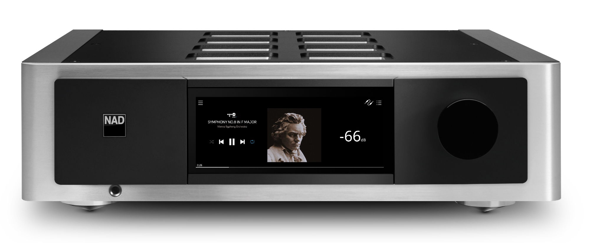
It contains streaming, conversion, room EQ, and wireless connectivity. The amplifier modules (Purifi) are merely one part of the whole package. People who buy an M33 don’t do so on the strength of the choice of amplifier alone. Selecting reputable parts for a new project increases customer confidence, but it’s still very much your company’s own unique product. You shouldn’t have to rely exclusively on the power stage to woo customers. If what you’re trying to sell consists of nothing but an off-the-shelf module in a box, that’s a self-inflicted problem.
Maybe the “dumb amplifier” as a product category has run its course. As a circuit, a power amplifier is a technological artifact. But a metal case with nothing but a mains inlet, a line input, and a pair of speaker terminals is a cultural artifact. Its existence is not predicated on our desire for nice sound in the house, but on how we’ve gotten used to doing Hi-Fi.
Remember how the schoolbook amplifier was undone by the fact that it consisted of separate blocks whose roles are cast in stone? The same myopia affects traditional Hi-Fi. You’ve got a “source”, a “preamp” an “amplifier” and a “speaker”. If you’re rich, you’ll want to split a digital source into, say, a streamer and a DAC which each in turn may be sold as one box with the works and another box with the power supplies (separate digital and analog power supplies, natch).
Does anyone really believe the increased “boxification” of Hi-Fi systems is making them better engineered? Is a pair of passive speakers with a veritable steampunk altar sitting between them the logical conclusion to a quest for the ultimate in musical realism? Why is a device that fulfills several functions seen as “budget” or “mid-fi” while a dumb monobloc amp can command an unlimited price?
Oh, they’ll tell you it’s to keep the various parts from interfering with each other. Anyone can see that the converse is true: if something as silly as a different power cord on a digital-only streamer causes an audible change, that proves the separates approach has spectacularly backfired and the whole wire jungle behind your Hi-Fi rack is cross-talking. It’s not a feature, folks. It’s a bug. Stop being proud of it and bury your heads in shame.
The real answer is crass commerce. If the customer can swap components at will, shops can sell upgrades at will. It’s called “the hobby”. You don’t buy a sound system; you start on a journey. One along which people seemingly lose the will to listen to music, witness the insipid gunk played at Hi-Fi demos.
The fundamental downside of exchangeable separates is that it precludes any kind of synergy. To clarify, consider the polar opposite, active speakers. By which I don’t mean passive speakers with the filters taken out and replaced by their active equivalent. Such toe-in-the-water products do no justice to what’s possible if you conceive a speaker to be active from the start and optimize the design to the hilt.
Active EQ lets you trade cabinet size for amplifier power, so you can make the product smaller. Digital phase correction lets you get rid of the time smear that’s a fundamental part of passive crossovers. Cleverly overlapping multiple drivers allows you to constrain directivity and reduce the impact of the room. Properly done, active speakers do things that are physically impossible for passive ones.
Sweeter still: active is cheaper: class D amplifier modules cost less than some inductors for passive crossovers. You can build something that runs rings around a top-flight separates rig and make it masquerade like a lifestyle product with a matching price tag.
Not a week goes by without some pundit asking, “Is high-end audio dying” and why we can’t get the younger cohort interested in high-performance audio.
Isn’t it obvious? A young couple accidentally strays over the threshold of a Hi-Fi shop where they are peremptorily informed that they’ll have to school themselves in amplifiers, DACs, speakers, “interconnects” (i.e. cables), power cords, and “system tuning” before they can even think about parting with their cash. Are you surprised they decide it isn’t for them?
Not long ago, a leading Hi-Fi magazine ran an editorial proposing to remedy the problem using some kind of starter products: simple turntables, minimalist class A amplifiers, and chunky speakers, lifted straight from the author’s 1970s dorm room. This is beyond cynical. The transparent aim was not to get younger folks interested in high-quality sound as such, but in tinkering with boxes. It won’t even work: when did kids ever get excited about the same thing their parents loved when they were young?
How about giving them what they came into the shop for? A system that reliably sounds good and doesn’t present them with unnecessary choices. Preferably something that requires nothing but a power cable and a phone to play music. Give them all the user-friendliness of their cheap wireless speakers and soundbars but combine that with heart- stoppingly beautiful sound.
It’s not the fact that high-end amplification has become a commodity that should force manufacturers to rethink their strategy. It’s the survival of Hi-Fi itself that they need to secure. Class D isn’t the revolution, and neither will it trigger one. Class D is there to help the revolution along.

Bruno Putzeys (4/4/1973) cut his engineering teeth by learning to code at age 10 and building valve amplifiers at age 16. His thesis work was a class D power amplifier with low timing distortion. He was hired by Philips to finish odds and ends on mini audio systems but quickly found employment researching class D amplifiers by refusing to do anything else. There he tried an adventurous range of topologies, in the end creating the circuit that became known as UcD.
Lacking a commercial outlet, he joined Hypex in 2004 where he made the circuit popular in the form of modules and invented the integrator windup prevention scheme underlying Ncore, but that has since found widespread use in the industry. Meanwhile, he co-founded Grimm Audio where he developed a discrete DSD ADC (AD1) and an active loudspeaker (LS1). He also co-founded Mola-Mola where he designed, alongside power amplifiers, the “Makua” preamplifier, “Tambaqui” discrete PWM DAC, and “Lupe” phono preamplifier.
In 2014 he left these enterprises to form Purifi and Kii Audio. At Purifi he develops the “Eigentakt” range of class D modules and collaborates with Lars Risbo on the company’s line of loudspeaker drivers. At Kii, he designs active loudspeakers, notably the “THREE” and “SEVEN” loudspeakers.
He is a keen amateur industrial designer, with injection molding being a specialty.
1 For the purpose of this text, I’m not really distinguishing between classes A, AB, and B as the underlying circuitry is the same. They can be lumped together as “linear amplifiers”.
2 I might have accidentally stopped that show by presenting, within an hour from each other, https://aes2.org/publications/elibrary-page/?id=13494 and https://aes2.org/publications/elibrary-page/?id=13498. Put together, the two can be summarised thus: “Here’s the perfect digital modulator you’ve been looking for. Too bad it’s pointless to build an amplifier that way.”
3 https://purifi-audio.com/blog/tech-notes-1/this-thing-we-have-about-hysteresis-distortion-3
4 https://aes2.org/publications/elibrary-page/?id=1832
5 https://linearaudio.net/sites/linearaudio.net/files/volume1bp.pdf
6 It has been done though, using a fast ADC to get feedback from the output signal into the digital domain where you can do adaptive filtering: https://aes2.org/publications/elibrary-page/?id=15218. A commercial product along similar lines (developed independently from this) is made by https://www.axign.nl/. Taken merely as a digital-input amplifier it’ll float your boat just as nicely as a class D module with a DAC in front. What makes it special is that it’s programmable. If you’re minded to design a closed-loop speaker controller, it may well be the ticket.
7 The small-signal case (50% duty cycle) was first described here: https://aes2.org/publications/elibrary-page/?id=13263. The generic case has been solved meanwhile too, but it’s too useful as a trade secret to publish it.