Vacuum tube amplifiers are beloved for their sonic qualities, but unlike transistor-based designs, they cannot drive loudspeakers directly. The reason is fundamentally mathematical: the mismatch between the plate resistance of tubes (thousands of ohms) and the load impedance of speakers (a few ohms). To resolve this, a carefully engineered output transformer is required.
Why an Output Transformer is Necessary – The Basics
- Impedance Matching
- Loudspeakers present a relatively low load impedance (commonly 4–8 Ω).
- Vacuum tubes operate with very high plate impedances, often in the thousands of ohms.
- Directly connecting a tube plate to a loudspeaker would result in negligible power transfer and severe distortion.
- The output transformer provides the impedance transformation—stepping down the high plate resistance to a low impedance suitable for driving a speaker efficiently.
- Voltage and Current Conversion
- Tubes naturally produce high voltage swings but relatively low current.
- Loudspeakers require the opposite: moderate voltage but significant current to move their voice coils.
- The transformer converts the high-voltage/low-current output into a low-voltage/high-current signal.
- DC Isolation
- The transformer prevents the DC plate voltage (hundreds of volts) from reaching the loudspeaker.
- Without this isolation, the speaker would be destroyed, and the amplifier would be unsafe.
Challenges in Transformer Design
While necessary, the output transformer can become the weakest link in a tube amplifier if not carefully engineered. Its limitations can introduce coloration, bandwidth restrictions, and distortion. Designing a high-quality transformer involves balancing conflicting requirements:
- Bandwidth
- Low-frequency performance depends on large core size and sufficient inductance.
- High-frequency extension requires minimizing leakage inductance and stray capacitance.
- Achieving both simultaneously is difficult; compromises often dictate the amplifier’s frequency response.
- Core Material and Saturation
- The magnetic core must handle large signal swings without saturating.
- Core materials (grain-oriented silicon steel, amorphous alloys, etc.) influence distortion, efficiency, and sonic character.
- Winding Geometry
- Primary and secondary windings must be carefully interleaved to reduce leakage inductance.
- Poor winding techniques increase phase shift and limit treble extension.
- Mechanical precision and consistent winding tension matter to keep capacitance predictable.
- Impedance Matching Accuracy
- The turns ratio must be carefully chosen to match the intended tube plate impedance with common speaker loads.
- Even small errors can alter frequency response and distortion.
- Power Handling and Heat
- Transformers must carry significant current without overheating.
- Wire gauge, insulation, and cooling all affect long-term reliability.
Consequences of Poor Design
A poorly designed output transformer can severely degrade amplifier performance:
● Restricted bandwidth: weak bass from insufficient inductance or rolled-off treble from high leakage.
● High distortion: core saturation adds low-frequency distortion, while winding imbalances increase harmonic and intermodulation distortion.
● Loss of transparency: excessive phase shift smears transients and alters stereo imaging.
● Audible coloration: the transformer imparts its own “fingerprint” on the sound if not engineered with precision.
The Mathematics – Note that the purpose of this section is not to teach anyone the math involved, but simply to show the precision that is necessary in designing the output transformer.
1. Impedance Matching
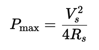
The maximum power transfer theorem states that maximum power is delivered when the load resistance equals the source resistance:
Where Vs is the source voltage and RS is the source resistance (here, the tube’s plate resistance RP).
● A typical tube has RP ≈ 5,000 Ω
● A speaker is RL ≈ 8 Ω
Directly driving the load yields:
With RP ≫ RL, almost no power reaches the speaker.
A transformer with turns ratio n = NP/NS transforms impedance as:
Thus, the tube sees a matched load, and efficient power transfer is restored.
2. Voltage and Current Conversion
Transformers obey:
● Tubes produce high voltage, low current (e.g., 300 V at 50 mA).
● A speaker requires low voltage, high current (e.g., 20 V at 2.5 A).
With n = 15, a 300 V swing on the primary becomes:
While the current is stepped up:
Matching the speaker’s needs.
3. DC Isolation
Tubes operate with plate voltages VDC ∼ 300–500 V.
The transformer blocks DC, since:
Or a steady current (transformers require a constantly changing magnetic flux, which occurs in the alternating current of music signals, in order to work).
Thus, the speaker sees only the AC audio signal, not the destructive DC.
Transformer Design Mathematics
1. Low-Frequency Response
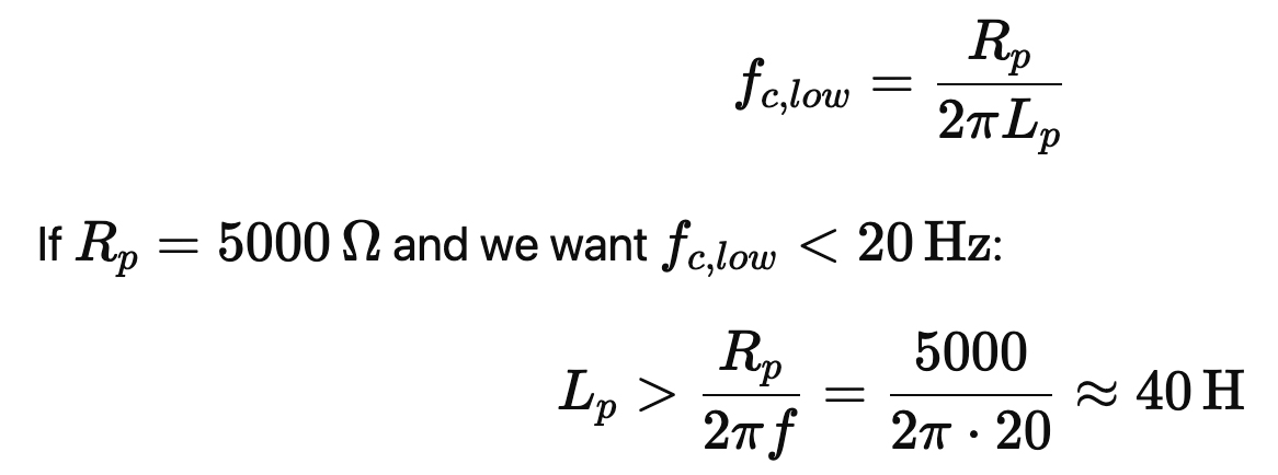
Primary inductance LP determines the low-frequency cutoff:
Large inductance requires many turns and a large core, which increases copper loss and capacitance.
2. High-Frequency Response
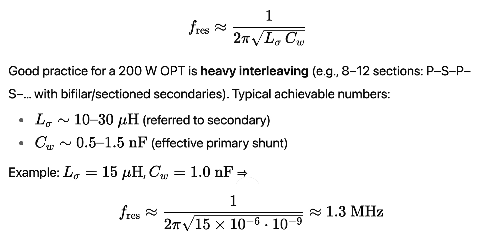
Leakage inductance Lσ and winding capacitance CW create a low-pass pole:
In practice, parasitics are worse, so achieving a flat response beyond 50–100 kHz requires careful interleaving of windings.
3. Core Saturation
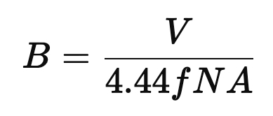
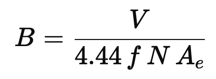
Magnetic flux density in the core is:
Where N is turns, A is the core cross-sectional area.
This exceeds typical steel saturation (~1.5 T), so more turns or larger cores are required—raising cost and size.
4. Phase Shift and Distortion
The transformer introduces a frequency-dependent phase shift:
Poor design yields group delay, smearing transients. Nonlinearities in the core’s B-H curve add harmonic distortion, especially at bass frequencies.
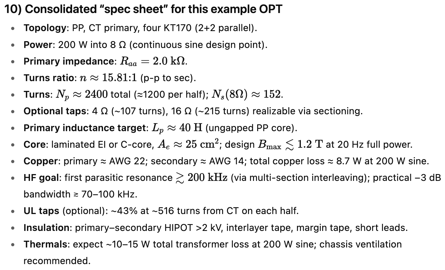
Here is an example output transformer design for a monoblock one-channel tube power amplifier with four KT-170 tubes in the output stage, push-pull, with two KT-170s in the + leg and two KT-170s in the – leg. The output of the amplifier is 200 Watts into 8 Ohms.
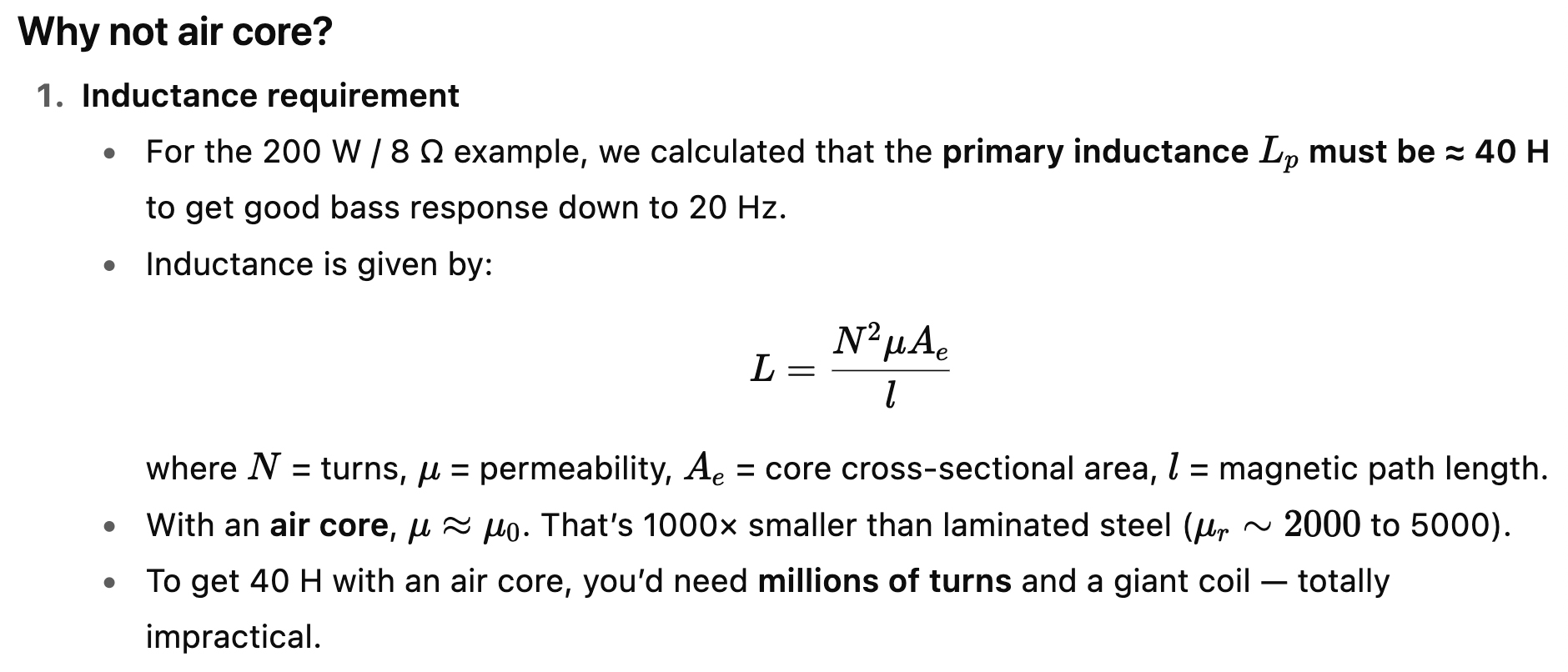
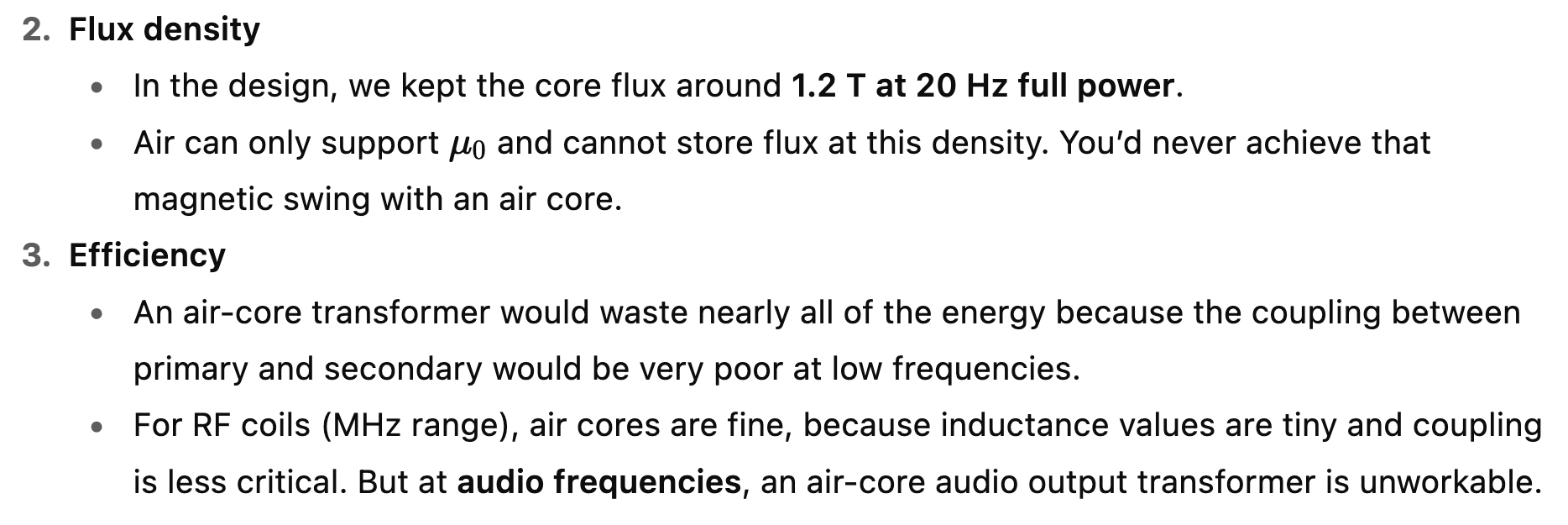
It will be a laminated solid-core design rather than air-core.
Air cores are only seen in high-frequency inductors (RF, crossovers above 10 kHz, etc.), not in power-band audio output transformers.
The core material in an output transformer is just as important as the winding design. Different alloys have different permeability, saturation limits, and loss characteristics.
Which is Best for a 200 W / 4×KT170 OPT?
● Practical choice: Grain-Oriented Silicon Steel (GOES), laminated at 0.23–0.27 mm for low losses
→ Strong bass, handles high flux, affordable, proven in high-power amps.
● Boutique upgrade: Nanocrystalline or Amorphous Alloy
→ Better HF clarity, lower distortion, but very costly and larger cores needed.
● Not practical: Permalloy
→ Wonderful transparency but unsuitable for 200 W due to low saturation flux density.
Here is a chart showing the performance characteristics for various core materials (click on the chart to enlarge it for clarity).
The Basics of Designing a 200 W Tube Amp Output Transformer
● 0. Target – The goal is 200 watts into an 8-ohm speaker, using four KT170 tubes in a push-pull arrangement.
● 1. Speaker Side – The speaker needs about 40 volts and 5 amps at full power.
● 2. Matching – The transformer must convert the tubes’ high-voltage, low-current output into the low-voltage, high-current signal the speaker needs.
● 3. Primary Impedance – The transformer should present about 2,000 ohms to the tubes, which matches the four KT170s in push-pull.
● 4. Low-Frequency Performance – To reproduce bass cleanly, the transformer needs a very large inductance, which means a lot of turns of wire and a large magnetic core.
● 5. Core Size – A big laminated steel core is used to carry the low-frequency magnetic energy without distortion.
● 6. Interleaving for High Frequencies – The primary and secondary windings are split into sections and layered together. This keeps treble clear and extends the high-frequency response.
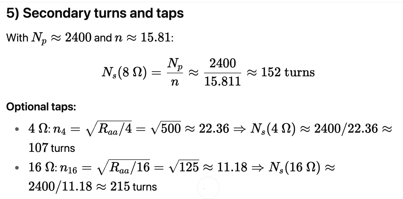
● 7. Secondary Windings – The secondary winding has taps for 4, 8, and 16 ohm speakers, made by using different turn counts or series/parallel connections.
● 8. Wire Size – The primary uses thinner wire (modest current), while the secondary uses thicker wire to handle several amps without heating too much.
● 9. Power Losses – Some heat is produced in the copper, but a good design keeps these losses small compared to the amplifier power.
● 10. Extra Features – Optional “ultralinear” taps let the screens of the tubes be connected for lower distortion. Insulation, varnish, and safety testing are essential.
● 11. Final Specs – The finished transformer is big (about 9–12 kg), expensive (hundreds of dollars to build), but absolutely critical to sound quality.
The Math:
0) Target and operating assumptions
● Rated audio power at the speaker: PO = 200 W into RL = 8 Ω
● Topology: push-pull, two tubes in parallel per half-primary (PP-parallel).
● B+ (design point to check your tube curves against): ≈ 600 V (typical for high-power KT170 AB1), screen either UL at ~40–45% or fixed screen; global NFB assumed but not needed for transformer math.
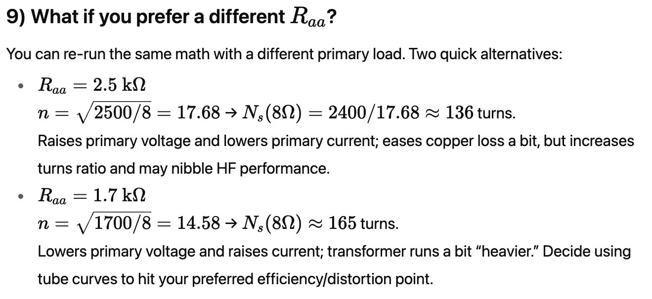
● We’ll choose a plate-to-plate (p-p) primary impedance Raa of 2.0 kΩ (good ballpark for 200 W with a quad of big bottles). You can nudge this up or down after you pick exact tube operating points from datasheets.
● True plate resistance rp is extremely high (tens of kilo-ohms, often quoted 20–30 kΩ or more).
● That’s why in pure pentode mode, the load impedance is determined more by design charts (optimum load Ra) rather than rp.
● For the KT170, datasheets suggest optimum load per pair ~3.4 – 4.0 kΩ p-p at typical B+ (600 V, 100 W class AB1). With four tubes in parallel (2 per side), that halves to ~1.7–2.0 kΩ p-p, which is exactly why we chose ~2.0 kΩ in the transformer design. In triode mode and ultra-linear mode, the plate resistance goes down to between 700 Ω and 4 kΩ, but so does the output power.
1) Secondary requirements (speaker side)
Power and current at the secondary:
These are the hard specs the secondary must deliver continuously at full sine power.
2) Choose primary impedance and turns ratio
Pick Raa = 2.0 kΩ plate-to-plate. For an ideal transformer:
● Turns ratio (whole primary to secondary): n ≈ 15.81.1.
Primary voltage and current at full power:
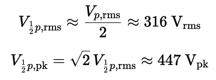
Because this is a center-tapped primary, each half-primary sees about half the p-p voltage:
That swing is compatible with a B+ near 600 V (plates will swing below and above B+ in a transformer-coupled stage).
Load seen by each tube
● The load presented to one half of the primary is Raa/4=500 Ω.
● There are two tubes in parallel per half, so each tube “sees” roughly twice that (current sharing):
That would be used to draw your per-tube loadline at the chosen B+, screen mode, and bias.
Secrets Sponsor
3) Low-frequency design → primary inductance Lp and core size
3.1 Set the LF corner
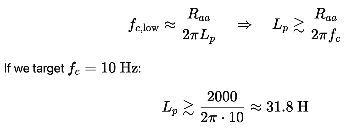
A common criterion is placing the low-frequency pole well below 20 Hz to minimize phase shift at 20 Hz. For a transformer loaded by Ra, the first-order corner is:
Design target: Lp ≈ 40 H (gives margin and reduces 20 Hz phase shift). (H = Henries)
3.2 Core flux and primary turns
We size turns Np so the core does not saturate at low frequency during high-level bass. Using the sinusoidal transformer relation (RMS):
Choose a conservative Bmax around 1.2 T for low distortion. The design will deliver full power at 20 Hz that won’t saturate (relax this to 25–30 Hz if you want a smaller transformer).
● Pick Np ≈ 2,400 turns total, i.e., ~1,200 turns per half-primary.
Cross-check vs inductance: with quality laminations (high μr, Np ∼ 2,400 and a core of this size can realize Lp in the tens of Henries; hitting ~40 H is very reasonable on an ungapped push-pull core.
3.3 Headroom vs DC imbalance
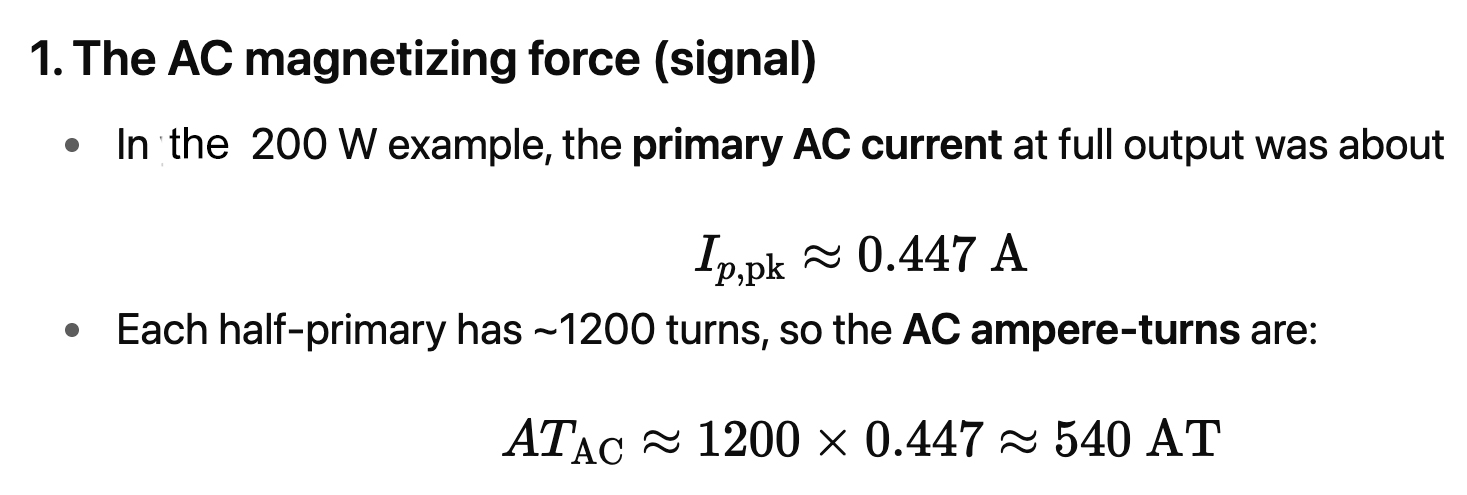
Push-pull primaries are not gapped (see NOTES), assuming DC plate currents cancel. Some imbalance budget should be allowed. Compare DC ampere-turns to AC ampere-turns at 20 Hz:
This small bias won’t materially choke LF headroom.
4) High-frequency design → leakage Lσ, capacitance Cw, interleaving
The dominant HF pole/zero comes from leakage inductance in series with the secondary and winding capacitances shunting the primary. A target is pushing the first parasitic resonance well past the audio band:
Plenty of margin; even with real-world spread, a flat response from 70 – 100 kHz is practical with proper sectioning and careful layer insulation.
A practical approach would be to wind two or four identical secondary sections (e.g., ~53 or ~76 turns/section) that can be series/parallel-configured to realize 4/8/16 Ω while balancing copper distribution and minimizing leakage.
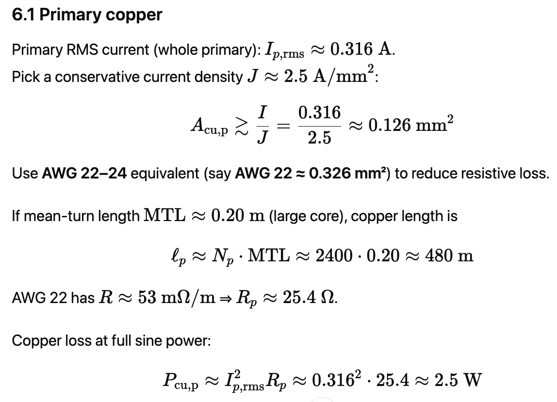
6) Copper sizing and losses (sanity check)
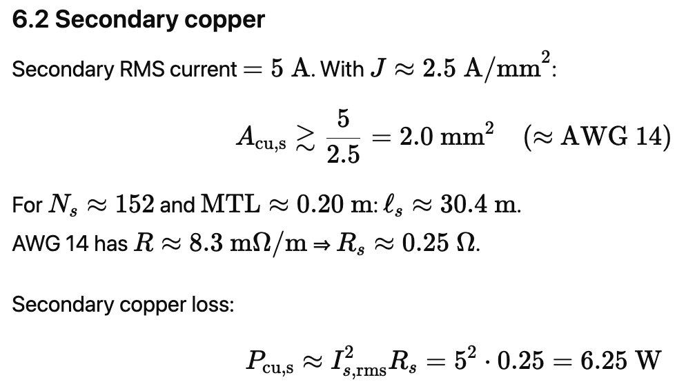
Total copper loss ≈ 8.7 W at continuous full sine is quite acceptable. Core loss in quality laminations at audio flux densities will be a few watts more, so transformer self-heating is manageable for a chassis-ventilated monoblock.
Place taps symmetrically on both halves; keep screen leads short. UL reduces effective plate resistance and distortion at the expense of a modest max-power reduction vs pure pentode.
8) Insulation, sectioning, and winding order (HF performance & safety)
● Sectioning/interleaving: e.g., 10-section stack: P1–S1–P2–S2–P3–S3–P4– S4–P5–S5 (mirrored to keep symmetry). This reduces Lσ and pushes HF extension out.
● Insulation: inter-layer paper/Mylar/Nomex; primary-to-secondary insulation to withstand >2 kV impulse (your plates will swing well above B+ on transients).
● Creepage/clearance: maintain margins on the bobbin walls; use tape margins at each layer edge.
● Electrostatic shield (optional): A Faraday shield between primary and secondary can reduce capacitive coupling of HF garbage into the speaker return.
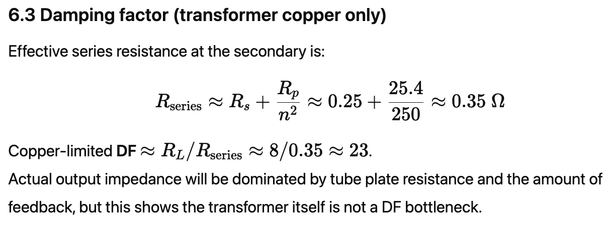
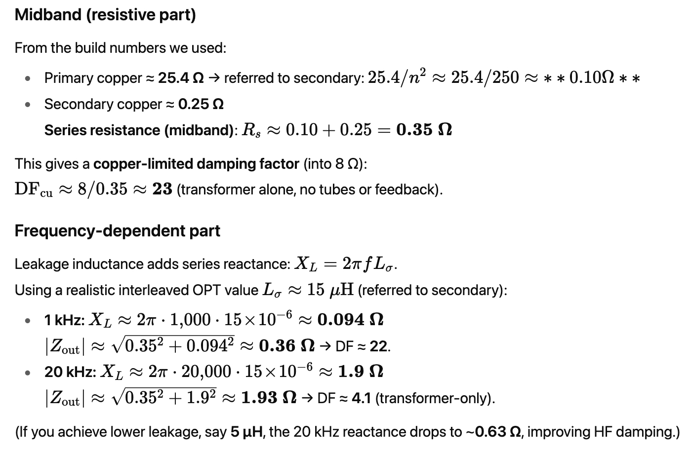
So, one of the output transformer’s main purposes is to reduce the output impedance going to the 8 Ω speakers. Here are the results:
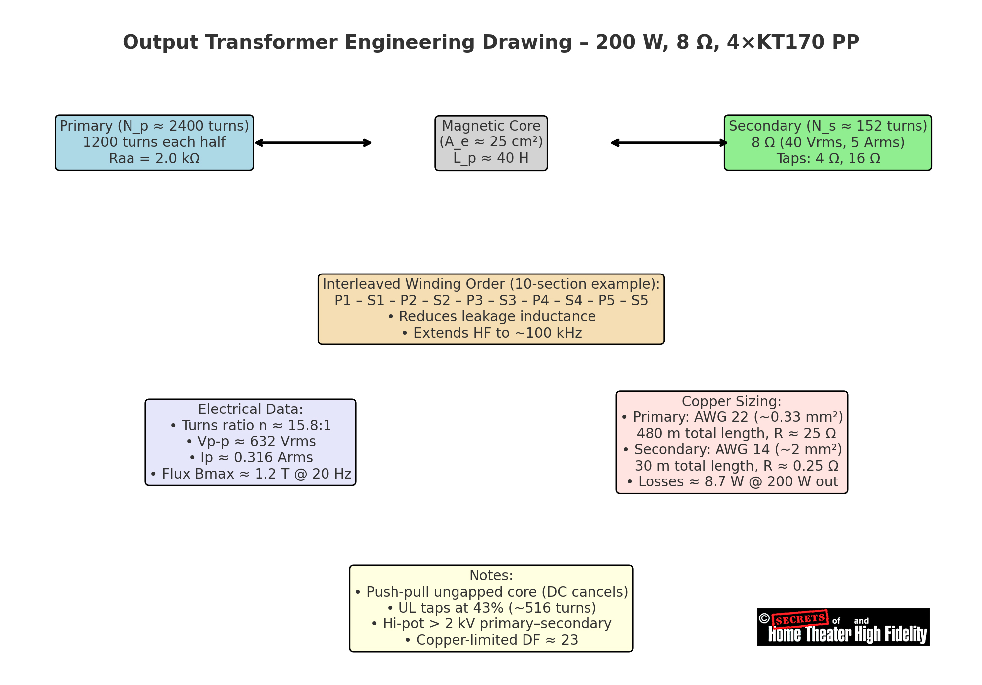
Here is a summarized diagram of the output transformer for a 200 Watt into 8-ohm monoblock power amplifier using four KT-170 output tubes in a push-pull configuration.
● Top row: Block diagram of the primary, core, and secondary.
● Middle: Layer/section interleaving order (P–S–P–S for low leakage).
● Bottom left: Electrical data (turns ratio, voltages, currents, flux).
● Bottom right: Copper sizing and winding resistance.
● Bottom center: Notes on UL taps, ungapped core, insulation, and damping factor.
The Cost of this Output Transformer:
Expect roughly $300 – $500 to build one (materials + labor) for the GOES (Grain-Oriented Silicon Steel) version in very small quantities, and retail (the added cost to the customer for this part of the amplifier) commonly lands around $700 – $1,500 each after overhead and margin. A boutique nanocrystalline version can run $700 – $1,200 to build and $1,800 – $3,500+ retail. It would weigh about 25 pounds.
In the statement, “Push-pull primaries are not gapped,” gapped” refers to whether the magnetic core of a transformer has a small air gap inserted in it.
1. What an air gap is:
● A transformer or inductor core is usually made from laminated steel.
● In a gapped core, the laminations are separated by a thin, controlled gap (air or non-magnetic spacer).
● This reduces the core’s effective permeability (μeff), which lowers inductance but dramatically increases the core’s ability to handle DC current without saturating.
2. Why this matters:
● Single-ended tube amps:
In a single-ended output stage, a tube passes current through the primary at all times (DC plate current plus AC signal). That DC biases the core’s flux. Without a gap, the core would quickly saturate, causing distortion.
So single-ended output transformers must be gapped.
● Push-pull tube amps:
In push-pull, the two halves of the primary carry equal but opposite DC currents.
Ideally, those DC magnetizations cancel out in the core.
Because of this self-cancellation, no gap is needed. A gapped core would just reduce inductance and hurt bass response, so push-pull OPTs are built on ungapped cores.
3. The tradeoff
● Gap present: prevents DC saturation, but reduces Lp (lower inductance, worse bass, more phase shift).
● Gap absent: maximizes Lp (better bass) but only works if DC cancels (push-pull).
AT = ampere-turns
It’s a unit of magnetomotive force (MMF).
MMF=N⋅I
where
- N = number of turns (dimensionless)
- I = current in amperes
So, 1 AT = 1 ampere flowing through 1 turn of wire. If you have 100 turns with 0.5 A, that’s 100 × 0.5 = 50 AT.
● T = turns (context dependent!)
When you see “1200 T” or “N = 2400 T”, it means 1,200 turns of wire.
But be careful: T can also mean Tesla when used for magnetic flux density B.
Example in transformer talk:
● “AC ampere-turns” means the alternating magnetizing force from the signal current.
● “1200 turns” is just the winding count of that half-primary.
● “1.2 T” means the flux density in the core (tesla).
So:
● AT = ampere-turns (MMF)
● T = turns (when describing winding count) OR tesla (when describing flux), the meaning comes from context.
Referring to the statement that DC imbalance ampere-turns were “~2% of AC,” it was comparing two magnetic forces in the transformer core:
This is the alternating magnetizing force that swings the core flux back and forth with music.
2. The DC imbalance force
In a push-pull stage, ideally, the DC currents from the two halves cancel out. But in real life, the tubes don’t match perfectly; say there’s 10 mA mismatch between the two sides.
That small imbalance gives a net DC current through half the primary:
ATDC ≈ 1200 × 0.01A = 12 AT
So, the unwanted DC bias is only about 2% of the normal AC drive force. That means it won’t push the core anywhere near saturation and is essentially harmless in a well-matched push-pull amplifier.
Secrets Sponsor
Mathematically, the mismatch between tubes and speakers makes an output transformer indispensable. A tube’s plate impedance, often measured in thousands of ohms, cannot efficiently transfer power into the few ohms of a loudspeaker without this crucial coupling device. The transformer is the bridge between two worlds: it converts high-voltage, low-current energy into the low-voltage, high-current drive required by loudspeakers, while also blocking hundreds of volts of DC from ever reaching a delicate voice coil.
Yet, the transformer is not merely a convenience; it is the single most demanding element of tube amplifier design. It’s physics, primary inductance to support bass, leakage inductance and winding capacitance that govern treble extension, and core saturation limits that dictate headroom, determine the amplifier’s real-world bandwidth, distortion floor, and transparency. Every design decision, from the turns ratio and interleaving pattern to the choice of core material and lamination thickness, is a balancing act governed by strict electromagnetic formulas.
A well-designed transformer can deliver a frequency response of 20 Hz – 50 kHz or more, with low harmonic distortion and stable impedance transformation that keeps the amplifier in control of the loudspeaker. By contrast, a poor transformer strangles bandwidth at both ends, introduces phase shifts and resonances, adds measurable distortion, and leaves its audible “fingerprint” on the sound. In high-fidelity tube amplification, the transformer is both the great enabler and the great challenge.
This challenge is not just technical; it is also economic. Building a high-performance transformer capable of handling 200 W of clean audio requires kilograms of copper and specialized magnetic steel, often grain-oriented silicon steel or even exotic nanocrystalline alloys. The core alone may weigh 6 – 9 kg, and the copper adds another 2 – 3 kg. With precision interleaving, insulation, impregnation, and high-voltage testing, the material and labor costs of a custom unit can easily reach $300 – $500 apiece for GOES steel, and more than $1,000 for boutique amorphous or nanocrystalline cores. In small-batch production, the final retail price often exceeds $700 – $1,500 per transformer, and in the high-end market, prices can climb into the several-thousand-dollar range for esoteric designs.
This cost is justified because the transformer is the component most directly responsible for whether a tube amplifier sounds effortless and natural or congested and colored. A world-class transformer preserves the linearity and harmonic texture of the tubes, delivering deep, controlled bass, open midrange, and airy highs. A mediocre transformer, no matter how fine the tubes and circuitry, will compromise the musical experience irreparably. For this reason, audiophiles and designers alike recognize that the transformer is the “soul” of the tube amplifier: the most expensive component to manufacture, the most technically exacting to design, and ultimately, the most decisive factor in determining sound quality.


