Let’s open our minds and think ‘inside’ the box, which in this case is the speaker enclosure itself.
The virtues of a great loudspeaker could be described as a full frequency spectrum where lows emerge from the abyss with enough dynamic range to champion a Hans Zimmer soundtrack. Add in timbral accuracy and the ineffable sense of reality (Steve Hoffman’s “Breath of Life”). Profound articulation and clarity are displayed in the upper-mids and treble via the utmost in acceleration. Last, but not least, a great loudspeaker system should portray a sense of venue: a truly four-dimensional recreation of space over time.
After more than four decades of daily research, design, and refinement, I can conclude that there remains more room for improvement in loudspeaker design than anywhere else in the audio chain. While designs today are overall significantly better than designs of fifty or even ten years ago, there is much potential unrealized. First and foremost, loudspeakers are dreadfully inefficient with typically 98% of the energy applied lost to inductors, resistors, voice coils, and mechanical losses. Passive crossovers typically consume 5% of the power applied for each order of crossover slope across the spectrum.
While an electric vehicle through traction can convert 80% of applied energy into propulsion, the impedance mismatch of a speaker diaphragm provides very little energy transfer to the low density of its air load. There is a similar impedance mismatch between air and the fluid within your inner ear. If it wasn’t for a remarkable lever mechanism provided by the bones in your ear, most of the sound would be reflected back at the eardrum.
While many of today’s amplifiers are more powerful, efficient, cost-effective, and physically more manageable, the same cannot be claimed for highly touted loudspeakers. With many flagship passive speakers approaching 500 lbs. each and prices exceeding the costs of a luxurious home, one can reasonably ponder what exactly is fundamental to loudspeaker performance and why the technological lag in high-end speakers. Legacy Audio, Kii Audio, B&O, Dutch and Dutch, and Genelec are among a limited number of speaker manufacturers embracing actively powered, DSP-steered directivity-controlled speaker designs.
Audiophiles recognize that high-end audio can be nostalgic while well knowing that real performance ultimately dictates progress forward. Some improvements such as higher resolution streaming and cloud storage are so profound that they become immediate successes. Just as analog tube TVs went to the curb with the onset of 1080p, vivid 8K video content promises 16 times the pixel count of 1080p. Performance steps forward.
Likewise, the inevitable future of stereo loudspeakers is direct streaming, DSP-controlled, environmentally adaptable, and actively powered. Home theater processing will continue to evolve with the newest mix methods and continue to benefit from digital processing just as live sound and even high-performance car audio. Fortunately, room correction continues to gain momentum and is a standard feature on most receivers and processors, and has found its way into automobiles.
Now for some fun!
The Fundamentals of Loudspeakers
There are many types of transducers ranging from electrostatics, air motion (Heil), planar magnetics, moving-coil, piezo crystal, plasma-ionic, thermo-acoustic, distributed mode, Radialstrahler, Walsh traveling wave, Geddes acoustic lever, along with just as many methods of loading them such as horns, dipole, gradient, acoustic suspension, transmission line, bandpass, etc. This brief discussion will focus on technological implementations that favor directional control, broad dynamic range, high sensitivity, and low distortion.
In a nutshell, the aligned goals for a great loudspeaker are wide bandwidth with solid bass foundation, uncompressed dynamics, proper timbre and clarity, spatial realism, and waveform tracking ability with time coherence and room adaptability. But how do we get there? And how do we accomplish this over a wide range of listening spaces? While a tall order, we can get there.
Driver Responsiveness
Just as high-performance vehicles must articulate the road ahead through acceleration and cornering, loudspeakers must closely track the complexity of music waveforms. But how much priority is really given to acceleration in speaker component selection? Well, in many cases not as much as you might expect. Since articulation is key in the midrange band let’s examine the acceleration capabilities of several midrange drivers found in high-end speakers.
Below is the calculated air volume acceleration (AVA) of these eight premium transducers.
AVA = motor assembly force product (BL) divided by moving mass (MMS) multiplied by effective cone area (SD)
The top three drivers listed are used in Legacy speaker designs. You might recognize the other five esteemed drivers as they are found in numerous high-end designs. Obviously, Legacy designs greatly emphasize the importance of acceleration with typically four times the acceleration volume of competitors. AVA is directly linked to efficiency, dynamics, and transient waveform tracing. This theme carries through the treble region with the high air volume displacement of the dual AMT arrangement and pleated diaphragms.
Going Low With Control
We all desire bass extension but initiating movement of a heavy woofer diaphragm is a bit like rocking a boulder out of a rut. It stores mechanical energy before lurching forward and yet must change direction 200 times per second at 100Hz. Additionally, the actual air particle velocity lags the surface pressure of the piston by 90 degrees and more. Each falling octave (halving of frequency) increases woofer excursion requirements by a factor of four, meaning that 20Hz requires 64 times the stroke length of 160Hz to maintain SPL. These strenuous demands are why three-way and four-way speakers can have significantly lower harmonic and intermodulation distortion. Note the upper range of harmonics which contribute to the timbre of bass instruments extends well above the fundamental tones.
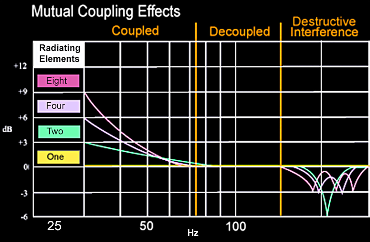
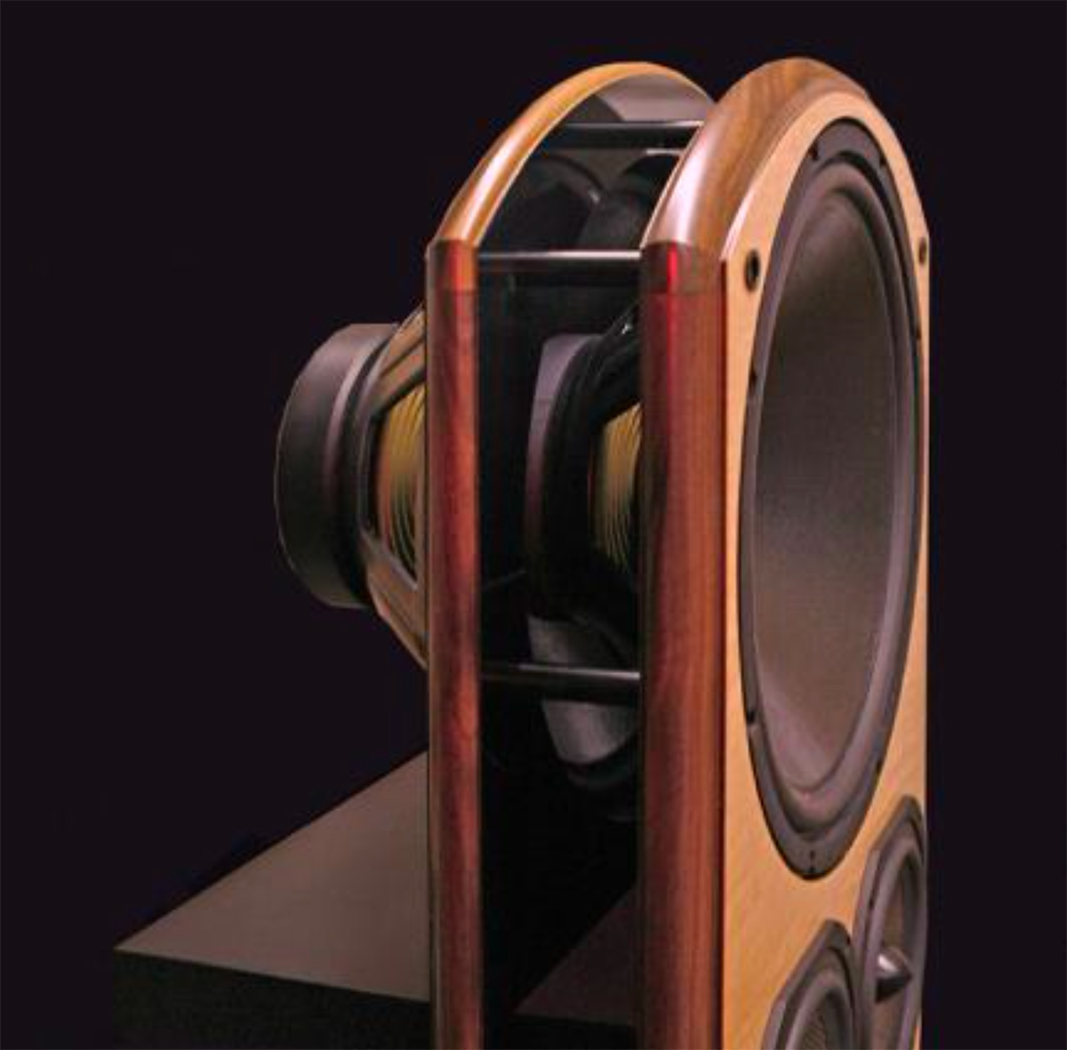
The best way to achieve deep bass is to have plenty of power available, a pair of mutually coupled woofers with their output mirrored off the ground plane with a low system resonant frequency. Mutual coupling adds 3dB of output for each doubling of driver elements. Fortunately for us all, kilowatts of clean, efficient power are now available, and DSP can adapt the woofers to both the enclosure and the room.
It is important to note that room modes can dominate at low frequencies emphasizing the advantages of using a time-domain based DSP room correction algorithm. Power equalization based on listener position is futile. Boosting a boundary-induced dip merely creates a peak at other listening positions while robbing power. This illustration below demonstrates that even moving a subwoofer around the room does not resolve the energy suck-out around 40 Hz due to a resonant node occurring at the listener position.
In this situation, a pair of subs placed on opposing side walls adjacent to the listener can be deployed with one side leading in phase by 45 degrees and the other side lagging in phase by 45 degrees which puts the subs in a quadrature relationship. Two sine waves 90 degrees apart sum in the original phase at the listener position yet resist the modal behavior due to their phase differences.
Secrets Sponsor
Frequency Range
The key to acoustic modeling is to think in terms of wavelength; the velocity of sound (1130ft/s) divided by the frequency of consideration.
Adequate piston area is essential at all frequencies to provide proper air volume displacement. Progressively increasing piston area with falling frequency is also key in directivity control maintaining linear dynamic range and low distortion levels.
Above 10kHz the wavelength is of the order of 1” while at 1kHz it has increased to about a foot, at 100Hz ten feet, and at 10 Hz about 100 feet. To maintain linearity the effective radiating piston diameter would increase in proportion with the growing wavelength, and the radiating area would increase with the square of this diameter. Scaling radiating piston diameter to frequency to maintain uniform directivity would obviously require an impractical size for an indoor speaker system.
Since distortion is proportional to cone displacement, dynamic range becomes restricted as frequency falls. Our Valor speaker for example deploys three 14” lower midrange. Overkill? Think again. This symmetric array provides the combined radiating area of a 24” piston width at bandwidth centered at 500Hz, where the wavelength just happens to be two feet. Linearity is maintained very nicely. But when we drop to 50Hz we would require a piston over 20 feet in diameter to claim the same. Fortunately, room gain through boundary reinforcement and cabin pressurization ultimately comes to our aid.
It is essential to take advantage of the ground plane (1/2 space) with woofer placement as it nearly eliminates floor bounce cancellations and increases the SPL by 6dB (the sound power level is increased by 3dB). Mutual coupling of a pair of drivers within a half-wavelength adds another 3dB due to increased radiation impedance.
Loudspeakers and the Listening Room
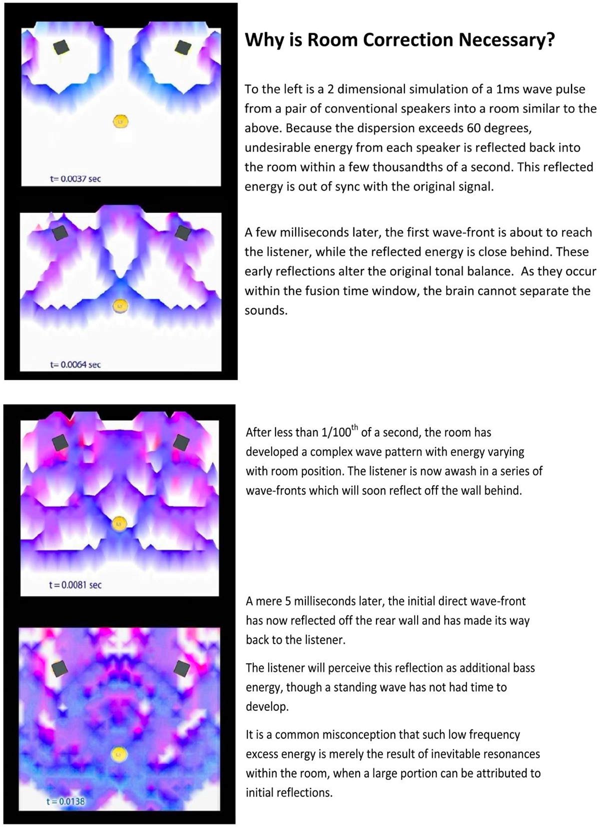
Faithful reproduction of a recorded performance benefits from a clear direct path from the loudspeaker to the listeners over the first 15ms. Diffuse energy arrival 25ms and later can reinforce spatial cues regarding the size and natural ambient energy of the venue.
Spatial properties derived by the listener’s internal processor (grey matter) include image size and placement, soundstage width and depth, or specific hall characteristics that are the result of the interplay of the stereo channels. The angle of arrival to each ear and the interference effects of the facial features and head contour (HRTF) determine the timing and amplitude differences. Also of enormous influence is the reflected energy of the room.
The Stereo Playback Process and the Loudspeakers
The only parameters recorded in audio are amplitude over time in each channel. Whether you refer to it as sound pressure level, intensity, volume, or merely a position on a VU meter – it is simply and precisely a single signal amplitude relative to a very specific point in time.
How the signal varies with time is where frequency, harmonics, attack, dynamics, melody, reverberation, and tone all arise. Think deeply about this, as a stereo recording of a complex 100-piece Marimba orchestra across a 120 ft stage is represented at any given instant merely as a pair of voltages for left and right. This illustrates that it is you, the listener, that tracks these amplitude changes over time, each instant recalled relative to the next with the brain deconvolving the matrix encoded. Preserving and recovering these precious vectors intact for your HRTF is key to maximizing the experience.
Imaging Quantified
The enchanting yet mysterious playback quality known as imaging or image localization is actually a result of precisely matched speakers with a focused radiation pattern that maintains an acoustic shadow to the far ear across your face. It is the difference in the composite signal reaching each ear that moves the image outwards from the center position (L+R or mono).
Legacy Audio employs a simple yet precise method of determining the imaging potential of a loudspeaker system by measuring its IMAGING INDEX. It is a test of the system’s correlation capability. You can apply it nearfield or at listener position. Beyond the critical distance, the room begins to dominate. This also illustrates the need for time domain- based room correction.
Secrets Sponsor
METHOD
With both loudspeakers equidistant from an SPL meter or test microphone, play a correlated pink noise signal (mono) at a reasonable level through both loudspeakers.
Begin with one of the speakers connected in reverse polarity and move the microphone a few centimeters to find the deepest null (lowest SPL reading).
Record this dB value, and now reverse the polarity so both speakers are in phase. Record the level on the SPL meter.
IMAGING INDEX = in-phase summation – out-of-phase summation
= 75.0dB – 65.9dB
= 9.4
You can view this method with the Legacy Whisper system
The Importance of Directivity Control
Whether that venue is the Troubadour, Red Rocks, Greek Theater, or Royal Albert Hall, great recordings should put you there! Minimizing early reflections is key to retaining spatial integrity in recordings. Applying directivity control in loudspeaker design and compensating room influences in the time domain allows a significantly more realistic level of performance to be attained.
Just as microphones can have various pickup patterns, loudspeakers can have similar radiation characteristics. The loudspeakers that exhibit the greatest imaging index will have the most uniform and controlled directivity. They will also provide the widest range of true stereo-listening positions. The cardioid and hypercardioid radiation patterns as shown are highly desirable and benefit the listener via reduced early side and rear wall reflections.
Cardioid radiation patterns can be established by summing a dipole with an omnidirectional transducer. Both drivers are front firing and in phase (+), while the dipole is open to the sides and rear and combines its rear radiation (-) with the omni (+) summing to a null. We have applied this approach to six of our home tower designs. In live sound to prevent bass spill-over onto the stage resulting in feedback howl, multiple subwoofers can be placed in an end-firing arrangement. Here the woofers are spaced one behind the other and the rearmost woofer fires first then the next sequentially. A delay is increasingly applied moving forward in the array synchronizing the wave-launch with the velocity of sound. The only direction the drivers sum maximally is forward. Similar to the shotgun mic with its tube side inlets. Once again DSP at work.
In 1995 Legacy Audio introduced the first full range high directivity loudspeaker, the Whisper System. Employing a differential dipolar array with a pair of symmetrical 15” bass drivers placed 4.9” behind the identical front array on a separate baffle. The rear array launched 0.36ms ahead of the drivers on the front baffle steering bass forward. The rear radiation backward was met with a single 12” sealed woofer on the back in phase with the front, reducing the rear wall interaction significantly. This loudspeaker has achieved the highest imaging correlation index recorded, creating a 65-degree horizontal radiation pattern and attenuating 40dB @ 90 degrees off-axis.
Don Keele presented his ground plane constant beamwidth transducer array (CBT) while at HARMAN. The curved array is divided into multiple sections exhibiting progressive shading via attenuation, radiation angle, and path length. Flip it upside down and you’ll recognize the similar array of technology that has become dominant in live sound over the past two decades. These complex DSP-steered flying line arrays are found in concert halls, convention centers, and arenas.
D. B. Keele, Jr., “Constant-Beamwidth Loudspeaker array,” U. S. Patent No. 7,826,622 (Nov. 2010).
Adapting the Speaker to the Room
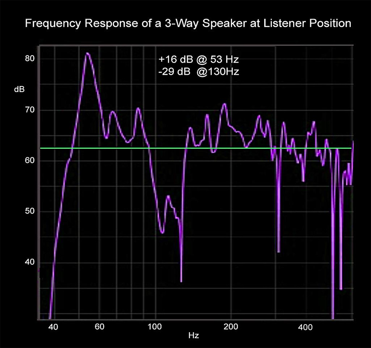
I have directly acquired measurement data from more than one thousand listening rooms over the past few decades which has directly influenced my speaker designs. A typical full-range loudspeaker will receive up to 12 dB of constructive room gain at very low frequencies, while exhibiting a 6 to 9dB room bump in the bass range below 100 Hz, with a strong dip between 100 and 130 Hz. A bookshelf speaker on a 28” stand will see a strong floor bounce cancellation around 275Hz thinning out the lower mids.
The measurement below applies to a three-way monitor in a compact recording studio where the owner was willing to change speakers or deploy room treatments to resolve booming bass and no impact in the upper bass, particularly in his left channel. Note the 45dB fluctuation over less than two octaves. Part of the problem was that this speaker’s 10” woofer was nearly the same distance from the floor, side wall, and wall behind the speaker. An additional problem is the midrange did not reach low enough to fill the single woofer dip at 130Hz, which would have been a great place to locate the crossover to transition the midrange. A proper filter slope and phasing strategy would improve the situation (second-order LP/HP with standard polarity reversal on the HP) as well as locating the woofer closer to the floor. See work by Roy Allison from (The Influence of Boundaries,1974, 48th AES Convention).
I favor 4-way designs where the bass drivers are close to the floor with a shallow low pass contour filter for pure reinforcement while underpinning a pair of symmetrical over and under dynamic mids. This alleviates the floor cancellation effect with the resulting summation lobes maximized at ear level while parallel to the floor. Tweeters are positioned at or slightly above ear level between the mids. On passive designs, I include a bass trim switch to prevent excessive upper bass from near boundaries and a treble trim switch for the near-to-midfield listener.
It’s About Time
The above exhibits in three dimensions the recorded strikes of a kick drum with its initial mechanical vibrations, harmonics, and resonances diminishing before the next strike. Pick any instant on the upper Timeline and follow the trail of reverberant energy on the Decay Timeline. When combined with a second stereo channel these subtle bits of information define the spatial characteristics of the environment.
A loudspeaker exhibiting a horizontal radiation pattern of approximately 60 degrees over its frequency range will prevent room sidewalls from masking these fragile spatial cues, and when toed inward slightly will easily cover a wide listening area via proper intensity trade-off.
The below image is the composite directivity pattern of a well-designed loudspeaker over a five-octave range. Though not a coaxial, the vertical pattern presents a surprisingly similar result. Very few loudspeakers can provide a similar directivity in the octaves below as a differential alignment with shading is required as with the Legacy Whisper XDS.


