DIY Project # 13 Audax Center Channel Speaker and a Discussion of Center Channel Speaker Design Engineering September, 2001 by Ralph Calabria
Introduction
Center channel speakers have come a long way since the first ones hit the shelves some years ago. I can remember when the only types of center channel speakers you had to choose from were either the standard monitor type (vertically oriented), or the “lay-the-speaker-down-on-its-side-so-it-doesn't-look-like-its-in-the-way” type (a.k.a. horizontally oriented). If you've ever tried to stand the latter vertically on top of your TV, you'll know what I mean! Most of the horizontally oriented speakers are pretty wide.
Well guess which one sounded better? The monitor, of course. This is due for the most part (all other things being equal with respect to quality) to a phenomenon known as lobing. When an MTM (Midwoofer-Tweeter-Midwoofer) design is laid on its side, the off-axis midrange frequency response is skewed, resulting in a frequency “dip”. This can happen with higher order crossover networks (3rd or 4th order), such as the ones that are typically used for MTMs, when the sound from one driver interferes with the sound of another. MTMs were designed to be vertically oriented because their main strength is good horizontal dispersion. When laid on its side, you get good vertical dispersion, but what good does that do when your sitting off axis, unless you happen to be on the ceiling or you're lying on the floor! Sitting out as little as 30° off the primary listening position (“sweet spot”), can cause a loss (dip) in the midrange frequencies.
This is not a good thing when considering that one of the main functions of the center channel is to accurately reproduce the midrange frequencies of the human voice. What's a designer to do? One way to get around the lobing problem is to arrange the drivers such that the tweeter is not in the horizontal plane with the midwoofers. Some designers have squeezed the midwoofers closer together, while raising the tweeter up off the center plane. A typical example of this design is the Paradigm CC300 (an older model that is currently in my system), where Paradigm was able to maintain a 4th order Butterworth crossover and still have decent horizontal dispersion. In order for Paradigm to accomplish this in a relatively short enclosure, they had to design a special tweeter with its flange cut away so the woofers can get close and personal with the tweeter. B&W went as far as removing the tweeter from the main enclosure and stuck it on top of the cabinet. Another way of getting around lobing is to reduce the order of the crossover (crossover slope). One of the more recent developments in center channel speaker design is to “marry” the vertically oriented speaker with the horizontally oriented one. Let's take a closer look at this approach.
3-way design
The “marriage” incorporates a 3-way design which eliminates the lobing problem and creates good horizontal dispersion because the tweeter and midrange are on the vertical plane. The tweeter and midrange are housed in their own little sub-enclosure, while the woofer(s) are in a separate enclosure, handling frequencies below the critical lobing frequencies. An example of this design on the market today is Boston Acoustic's (BA) Lynnfield series VR920 center channel ($599.95). To achieve this design in a relatively small cabinet, BA uses an almost flange-less 1” soft dome tweeter, a small 3 ½” midrange, and woofers that are oblong shaped (5 ¼ x 7 ½), which look a lot like car speakers.
Boston Acoustic VR920
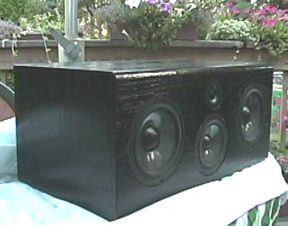
The Audax center channel
Audax contracted Dr. Joseph D'Appolito (JD), the world renowned speaker designer and creator of the MTM design, to put together a home theater package using Audax's new polymer chassis shielded HDA (High Definition Aerogel) cone drivers. The HDA drivers use the same cone material used on their more expensive Prestige Series drivers, but offer them at a cheaper price by using a polymer chassis. The package consists of a left/right speaker design, center channel (the topic of this review), monopole surrounds, and a subwoofer.
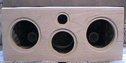
The center channel design incorporates the 3-way system described above. JD decided to make a full-range speaker, which uses two 6.5” AP170Z0 woofers, a 5.25” AP130Z0 for the midrange, and the Micro Series 1” soft dome tweeter. The tweeter is really small because it has no flange to speak of, which makes it ideal for this design to keep the cabinet height as low as possible. I should let you know up front though, you'll need some extra room to fit this speaker into your system, (or perhaps you're in the market for a new TV stand!) Either way, consider the dimensions of this speaker before you fire up the table saw.
The 30-liter woofer enclosure is ported, tuned to 49 Hz by using two 2” I.D. ports 5”each in length. The midrange enclosure is a 6-liter sub enclosure which also houses the Micro tweeter. Audax's measurements claim on-axis frequency response within +/-1.5dB from 100 Hz to 20 kHz. The F3 is 50 Hz, sensitivity is 87.5 dB at 2.83v/1m, and impedance is 7.5 ohms throughout most of the frequency range. Crossover frequency between the woofers and midrange is 400 Hz, and 3.5 kHz to the tweeter. This speaker should kick out 105 db SPL in an average sized room.
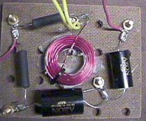
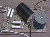
Crossover construction
It's important to use good quality crossover components. After spending a lot of time and money on building your cabinet to make it as acoustically dead as possible, you don't want to skimp on the crossover network. For this speaker, the cost of the crossover parts (and associated essentials) is almost the same as for the drivers. I got all my Xover parts from Zalytron. They offer Axon capacitors and resistors, and Erse inductors. I think Ohmite resistors are a little better, but Axon offers a good price/quality ratio, especially when it comes to their caps. I maintained the inductor gauge as described in the design and avoided using a lower gauge (thicker). There are different philosophies to this, but I was willing to take Joe D'Appolito's word for it when he said that changing the DC resistance of the system will affect the overall Q of the system, which ultimately will affect the sound!
Tweeter Crossover |
Midrange Crossover |
Woofer Crossover |

Here are the schematics for the woofer, midrange, and tweeter crossovers, respectively (Courtesy of Audax America).

(Diagram Copyright Audax of America)
If you go to the Audax website, you'll find a picture layout of the crossovers to get a feel for how the parts will be arranged on the board. I used the same techniques as in DIY#1 http://www.hometheaterhifi.com/volume_3_3/v3n3d.html#crossover to assemble the boards. Refer to this link of the article for details. When assembling the midrange board, use the schematic shown above and NOT the picture layout on the Audax website. On their picture layout, C2 and L2 are switched. Planning ahead for any project may avoid pitfalls you may stumble upon during the construction process. A good example of this is taking into account the overall size of the midrange board; it's 6” x 7”! That's a big board! So big, it won't fit into any of the holes in the cabinet! You may be able to make the board a LITTLE smaller, but considering all the components on the board, it may be tough to get it small enough to fit into one of the woofer cutouts. So, before you glue up the last wall of the cabinet, decide where the midrange board is going, and install it. I've warned you! The woofer board calls for 10 ohm, 25 watt resistors. To accomplish this, I used two 20 ohm, 12 watt resistors in parallel. Hooking up resistors in parallel will half the resistance, but double the power loading.
The cabinet
If I had to rank the complexity of building this cabinet, I would say, on a scale of 1-10, it would be a 6.5, with 1 being stone-cold easy. Any 3-way will be a little more difficult to build just by virtue of the sub-enclosure and the extra crossover network you have to assemble. However, as I mentioned earlier, if the sequence of the construction is done in the proper order, it really is pretty simple. A little forethought goes a long way in this project.
As usual, I just couldn't stand to follow the original cabinet plans that were given on the Audax website. I had to tinker at least a little, and I encourage anyone to do the same.
The first thing I noticed about the original plans was that there was no bracing. With a speaker cabinet this size, there should be. Of course, adding bracing will require a slightly larger cabinet, and since this cabinet is already large to begin with, one must be very careful not to overdo it. The major deviations from the original plans were: replacing the 1” MDF front baffle with a 1 ½” composite baffle of ¾” MDF and ¾” baltic birch (BB) plywood; replacing the ¾” MDF back with the same 1 ½” composite as the front; and adding two braces between each side of the sub-enclosure and the side walls. Even though these braces are only 1” wide all around, they made a huge difference in the sound deadening effect of the sides, top and bottom walls. Adding these extra braces only required increasing the internal depth of the speaker by ¼”, well worth the extra space. I increased the thickness of the front and rear panels so I wouldn't have to add any braces across the depth of the cabinet.
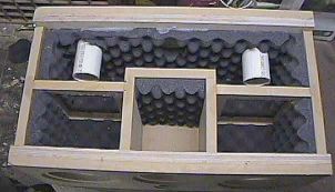
As I mentioned before, to a certain degree, the sequence of how things come together makes the construction process easier. Here's how I put the cabinet together, which worked out well. I cut all the wood necessary to make the cabinet with the exception of the braces (you'll see why!) I glued the front and back composites (MDF/BB plywood) and allowed the yellow glue to dry for about 24 hours. I then framed out the sides and top piece and glued them. As in previous projects, I used corner braces to hold the pieces aligned, glued the pieces, and used drywall screws to pull the corners together. I removed the corner braces and moved to the next joint. I then made all the driver holes, terminal cup hole, port holes, and flush mounting inserts for the driver before gluing anything else to the main enclosure. This is prudent, because a cutting mistake is much easier to correct when the baffles are not glued to the cabinet! I glued the ports on the back baffle using liquid nails. I then glued the front baffle on, ensuring that the proper alignment of the tweeter hole is positioned up toward the top wall. This was important in my project because I planned to add acoustical foam to the sides, back, and top of the cabinet. Since this is more easily done with one side off, it made sense for the side off to be the side where I wasn't going to add foam. The plans indicate adding foam to either the top OR bottom, but not both. If you choose to add the foam to the bottom of the cabinet, then reverse the front flange such that the bottom is assembled first and the top is the last piece to put on. I then assembled the sub-enclosure sides and back separately. After the glue dried, I removed the drywall screws and installed the sub-enclosure into the main box. Try your best to position the box in the center such that the distance between the main cabinet side walls and the sub-enclosure side walls are equidistant. If you don't get it perfect, don't worry, as long as it's close, it will be fine.

Cabinet with sub-enclosure installed
This is the reason for not cutting the braces yet, as they may be different lengths, depending on how close you center the sub-enclosure. Gluing this part was made easy by using some long clamps to hold the sub-enclosure tight to the front baffle and top panel. The back composite piece was then glued on. I then measured for the two braces (I missed it by 1/32”!) I cut the braces such that they fit just snug into the cabinet, then glued them in. At this point, the only cabinet piece not assembled was the bottom. I then measured the acoustical foam, and used yellow wood glue to put the foam on the sides, top, and back of the main enclosure, as well as the back of the sub enclosure. Yellow glue works great with the foam if you apply a thin film to the entire back of the foam. The foam soaks up the moisture of the glue and makes is instantly tacky.
Now where do I put that midrange crossover? Without braces in the cabinet, it was really tough to figure out where to put this beast. With braces, there was only one viable solution; stick on the back (outside) wall of the sub-enclosure. It fits just right there without getting in the way of the back terminal cup. If for some reason, the crossover fails (not likely if you use quality parts) it will be tough to get at it, so make sure the network is assembled properly before gluing. I used liquid nails and held it in place with four braces until the glue dried. I then drilled a small hole (small enough for four wires to make their way through) on the side of the sub-enclosure, and routed the wires to be connected to the midrange driver (from the crossover) through the hole.
Cabinet with foam and braces
The last piece of MDF was glued on. For this last piece, I made center lines on the bottom where I could put some drywall screws to pull the sub-enclosure and braces tightly against the bottom. Make sure to put glue on the braces and sub-enclosure to get a good seal.
When all the joints were dry, I backed out all the screws and filled them with wood patch. The entire cabinet was then sanded using a random orbital sander until all butt-joints were completely flush. I then used a ½” roundover bit on a router to round out the top front of the cabinet. Since the bottom of the cabinet is going to sit flat on top of the TV, routing the bottom isn't necessary.
Cabinet finishing
As I've mentioned in previous articles, I love the look of real wood. However, matching the wood look to my mains and sub, would make the speaker stand out on top of my big black TV. So I decided to make the speaker black to have it blend with the TV. Spray painting something black has its place in life, but not for my center channel. I wanted something a little more “grand”, as in "piano"! After doing some research on the topic of black piano finishes, I decided to have east meet west. I still used wood veneer, but dyed the wood black using an aniline dye.
I chose a 10 mil paper-backed red oak veneer to match the grain of my A652s and Titan sub. I applied the veneer using the dried wood glue and hot iron technique as described in previous projects. For a detailed description of this technique, check out DIY project #1 at http://www.hometheaterhifi.com/volume_3_3/v3n3d.html and the Titan project (DIY#8) at http://www.hometheaterhifi.com/volume_5_2/diy8titansubwooferjune98.html for improvements to the process. I veneered the bottom first, then the back, the sides, and finally the top/front as one piece, taking advantage of the roundover edge. All edges were lightly sanded until a seamless edge was produced.
Veneered cabinet
Once the veneer was scraped and lightly sanded, I stained the cabinet with a water based aniline dye. I applied three coats in order to get the color black I was going for and to completely cover the grain. I then lightly sanded once again to smooth out any grain that was raised by the dye. The advantage of dye over paint is that you still see the wood grain with the dye. Once you get to this point, there are several avenues to travel to get to a high gloss finish. I chose to use a French polish technique, which basically is shellac in alcohol, applied with a “rubber” instead of a brush. This type of finish is used on the finest of furniture and antiques, but is more of an art than anything. The end result is a mirror-like finish with just a few coats of shellac. As I'm not a pro at this, I've included a few links in the bibliography section at the end of this article, regarding French polish, that I found very useful. You build up the coat by continuous applications of the shellac. This takes time and patience, two commodities which were wearing very thin at the end of this project. I wound up applying five coats and stopped there. You can still see the wood grain, and I liked that. Shellac is a resin made from the shells of insects. It is soluble in alcohol and therefore, although it is exquisite, it is vulnerable to such things as a wet wine glass sitting on it, so be careful.
Installing the crossover boards, drivers, terminal cup and stuffing
I put the tweeter crossover on the floor of the sub-enclosure, routing the terminal cup wires through the hole I drilled and out the terminal cup hole. I installed the woofer crossover on the outside side wall of the sub-enclosure. Both boards were secured using Liquid Nails. The hole in the sub-enclosure where the crossover wires were snaked was sealed using silicone glue. Use plenty of glue here, as a good seal is critical to the performance of the midrange driver. I let everything dry for about 24 hours before installing the drivers because the Liquid Nails contains hydrocarbon solvents that may have an effect on the rubber surrounds of the woofers. Foam gasket material was placed around each driver cutout, and some polyester batting was placed in the sub-enclosure. The driver wires were lightly soldered to the respective terminals (don't over-do the heat here, as the terminals will melt!!!) The midrange driver was installed in the cabinet using #8/1” black panhead screws. The terminal cup wires were then lightly soldered onto the cup, and the cup was installed in the cabinet using standard terminal cup screws. The tweeter was also installed using terminal cup screws, and then the woofers were installed using #8/1½” panhead screws. All that's left is plugging it in
The grille
Grille? Grille? We don't need no sticking grille! Since this speaker is pretty much out of harm's way (i.e., away from curious kids and pets, poking and prodding about) on top of my RPTV, and I like the way the front of the speaker looks without a grille, I decided not to make a grille for this speaker at this time. If you decide to make a grille, I refer you to DIY # 1 for a possible way to fabricate it. Serious listening should always be done with the grille removed anyway!

The sound
After breaking in the drivers for a few weeks, I sat down and did some serious listening. I chose some heavy dialog scenes from various movies and monitored off axis mid-frequency loss. No matter where I sat in my listening room, the voices was very natural and clear. One thing that is noticeable on 2-way center channels is the “chestiness” in voices. That's because the large woofers are forced to reproduce the midrange voices as well as any lower frequencies. Also, the front of the TV can add loading. With this 3-way, the smaller midrange is dedicated to just midrange, making dialog much clearer. As for the dynamics of this speaker, it pretty much matches my left/right front speakers, pounding out at least 105 db without a hint of distortion. Special effects and music coming from this speaker also sounds clean, clear, and very detailed.
Cost estimate
Here is a breakdown of the overall cost of the project. I had a lot of the hardware materials left over from my last project. I didn't include them in the price, however, I did give a unit cost so these may be added should one not have these materials around. Since materials cost vary from region to region, your cost may differ somewhat.
| Unit Price | Unit of measure | Amount Used | Total Price | Vendor | |||
| Per Pair | Per pair | ||||||
| Drivers: | |||||||
| Audax 6.5" AP170ZO | $35.10 | ea. | 2 | $70.20 | Madisound | ||
| Audax 5.25" AP130ZO | $31.95 | ea. | 1 | $31.95 | Madisound | ||
| Audax 1" micro tweeter TM025F1 | $19.10 | ea. | 1 | $19.10 | Madisound | ||
|
Driver Subtotal: |
$121.25 | ||||||
| Cabinet and Grille Materials: | |||||||
| 3/4" Medium Density Fiberboard | $0.66 | square ft. | 9.50 | $0.00 | Lumber Yard left over | ||
| 3/4" Baltic Birch Plywood | $1.54 | square ft. | 3.50 | $0.00 | Lumber Yard left over | ||
| 2" I.D. PVC Pipe | linear foot | 0.83 | $0.00 | Van Hout Plumbing | |||
| Gold Plated Binding Posts w/Back Plate | $4.00 | each | 1 | $4.00 | Zalytron | ||
| Carpenter's Wood Glue | $5.49 | bottle | 1 | $0.00 | Home Depot left over | ||
| GE Silicone II Sealant | $2.97 | tube | 0.5 | $0.00 | Home Depot left over | ||
| 1 1/4" Dry Wall Screws | $2.30 | pound | 0.25 | $0.00 | Home Depot left over | ||
| Speaker Mounting Screws | $0.00 | each | 24 | $0.00 | Gift | ||
| Neoprene Gasket Tape | $0.25 | linear foot | 3 | $0.75 | NCMS | ||
| Grille Cloth | $7.95 | 36" x 67" | 0.25 | $1.99 | Parts Express | ||
| Particle Board for Grille Frame | $0.47 | square ft. | 3 | $0.00 | Home Depot left over | ||
| Mushroon Grille Fasteners | $2.50 | set of 4 | 1 | $2.50 | NCMS | ||
| Acoustical foam | $3.95 | 24" x 36" | 1.0 | $3.95 | Parts Express | ||
| Red Oak Veneer (paper backed) | $2.06 | square ft. | 10 | $20.60 | Lumber Yard | ||
| Black aniline dyes | $4.99 | ounce | 1.0 | $4.99 | Home Depot | ||
| Shellac | $6.99 | quart | 1.0 | $6.99 | Home Depot | ||
| Polyester Batting | $5.99 | 1 pound | 0.25 | $0.00 | K-Mart left over | ||
|
Cabinet and grille Subtotal: |
$45.77 | ||||||
|
Crossover Parts and Wire: |
|||||||
| L1 6.8mH, 0.48 Ohms; iron core | $5.99 | ea. | 1 | $5.99 | Zalytron | ||
| L2 1.2mH, 0.34 Ohms; 16 g air-core | $8.68 | ea. | 1 | $8.68 | Zalytron | ||
| L3 2.7mH, 0.53 Ohms; 16 g air-core | $12.94 | ea. | 1 | $12.94 | Zalytron | ||
| L4 0.27mH, 0.53 Ohms; 18 g air-core | $2.57 | ea. | 1 | $2.57 | Zalytron | ||
| C1 Capacitor 62µF Polypropylene | $11.68 | ea. | 1 | $11.68 | Zalytron | ||
| C2 Capacitor 24µF Polypropylene | $5.38 | ea. | 1 | $5.38 | Zalytron | ||
| C3 Capacitor 10µF Polypropylene | $2.90 | ea. | 1 | $2.90 | Zalytron | ||
| C4 Capacitor 82µF Polypropylene | $14.65 | ea. | 1 | $14.65 | Zalytron | ||
| C5 Capacitor 4.7µF Polypropylene | $1.76 | ea. | 1 | $1.76 | Zalytron | ||
| R1/R2 Resistor 10 Ohms; 12 Watts | $2.70 | ea. | 2 | $5.40 | Zalytron | ||
| R3 Resistor 8 Ohms; 12 Watts | $2.70 | ea. | 1 | $2.70 | Zalytron | ||
| R4 Resistor 15 Ohms; 12 Watts | $2.70 | ea. | 1 | $2.70 | Zalytron | ||
| R5 Resistor 2 Ohms; 12 Watts | $2.70 | ea. | 1 | $2.70 | Zalytron | ||
| 1/4" Peg board | $0.44 | square feet | 1.50 | $0.00 | Home Depot left over | ||
| 14 g Silver-coated Wire | $0.40 | linear foot | 24 | $9.60 | NCMS | ||
| Silver Solder | $1.50 | foot | 2 | $0.00 | NCMS left over | ||
| Brass Screws with nuts | $0.30 | set | 16 | $4.80 | Home Depot | ||
| Ring Crimp Connectors 10/12 G (#10 stud) | $0.20 | each | 18 | $0.00 | NCMS left over | ||
|
Crossover Subtotal: |
$91.88 | ||||||
| Grand Total: | $258.90 | ||||||
As you can see, my total cost of this project was about $260. If you don't have some of the things I had lying around, it will cost you a bit more, but the drivers and crossover parts are the big chunk of the cost. Regardless, if you were to buy this center channel speaker on the market, it would probably cost $1,000. For one, only the most costly speakers are this well built with really good quality crossover parts, not to mention the beautiful finish. Try rapping your knuckle on a $260 speaker, and you'll get the idea! Although building any cabinet is pretty straightforward, it takes time and resources. If this design fits your needs, but you've got neither the time nor the resources to build the cabinet, fear not. There are a couple of places you can purchase the cabinet already assembled and ready to install the drivers and crossovers. Madisound and Zalytron are two online stores that offer the cabinet. Zalytron's cabinets are hard to beat in terms of build quality and cosmetics, however, they are quite expensive (and worth it in my opinion). Madisound's cabinet is less expensive, but not built as sturdy. Check out the bibliography section here for their websites. If you're on a budget, Madisound offers the crossover parts at a cheaper price, but the old adage holds true here: “You get what you pay for!” And if you're soldering-impaired, they will also sell you the pre-assembled crossover boards for a nominal fee.
Final remarks
The cabinet construction that I've included here is fairly easy to reproduce if you follow the proper sequence. If done properly, you should run into no surprises. Let me also say that this speaker may not be for everyone. As I've mentioned before, it's big (height). Check out your space to see if it will fit in your home theater setup. If you can get over the big size of this speaker, you'll really get to appreciate the big sound it produces, and at a very affordable cost. Remember, the center channel is the most important!
Bibliography
Audax website that contains the entire home theater design package, including cabinet details of the center channel design:
http://www.audax.com/doit/us_ht01.shtml
French polish techniques and shellac use in general:
http://www.wwforum.com/faqs_articles/shellac.html
http://www.rustins.co.uk/FrepApp.html
http://www.shellac.net/index.html
Audax center channel pre-made cabinet:
http://www.madisound.com/audaxhometheater.html
- Ralph Calabria -
Magazine Publishing Solutions by