Here is the inside of the video processor.

The digital-to-analog conversion is handled by Analog Devices AD1853 DACs. These 24-bit, 192 kHz multi-bit Sigma/Delta converters are used in a
dual differential configuration for the eight main output channels, meaning
that each of the eight channels is fully balanced. The DACs
used for the remote zones are not specified; however, they are stated to be
24-bit, 192 kHz capable. To maintain the full resolution of these DACs, a
digitally controlled analog volume control is used.
All digital audio signals pass through a jitter rejection stage where
incoming data are buffered and re-clocked. FIFO stands for first-in,
first-out which is needed to maintain the causal relationship of the
incoming data. The data re-clocking ensures that the data are leaving the
FIFO at a constant rate. ML calls their implementation an "Intelligent
FIFO".
I/Os
The back panel of the No 40 provides a look which is
different from most processors that are out there. The connectors are neatly
arranged either vertically or horizontally depending on the orientation of
the card. The expanded real-estate which comes from having two-chassis also
allows good spacing between the connectors. This is unlike most processors
where you get a busy look with tight spacing between the connectors. Most
processors are not hardware upgradeable, so they need to build in the
maximum number of connectors that anyone may need rather than making the
number of connectors configurable via upgrades.
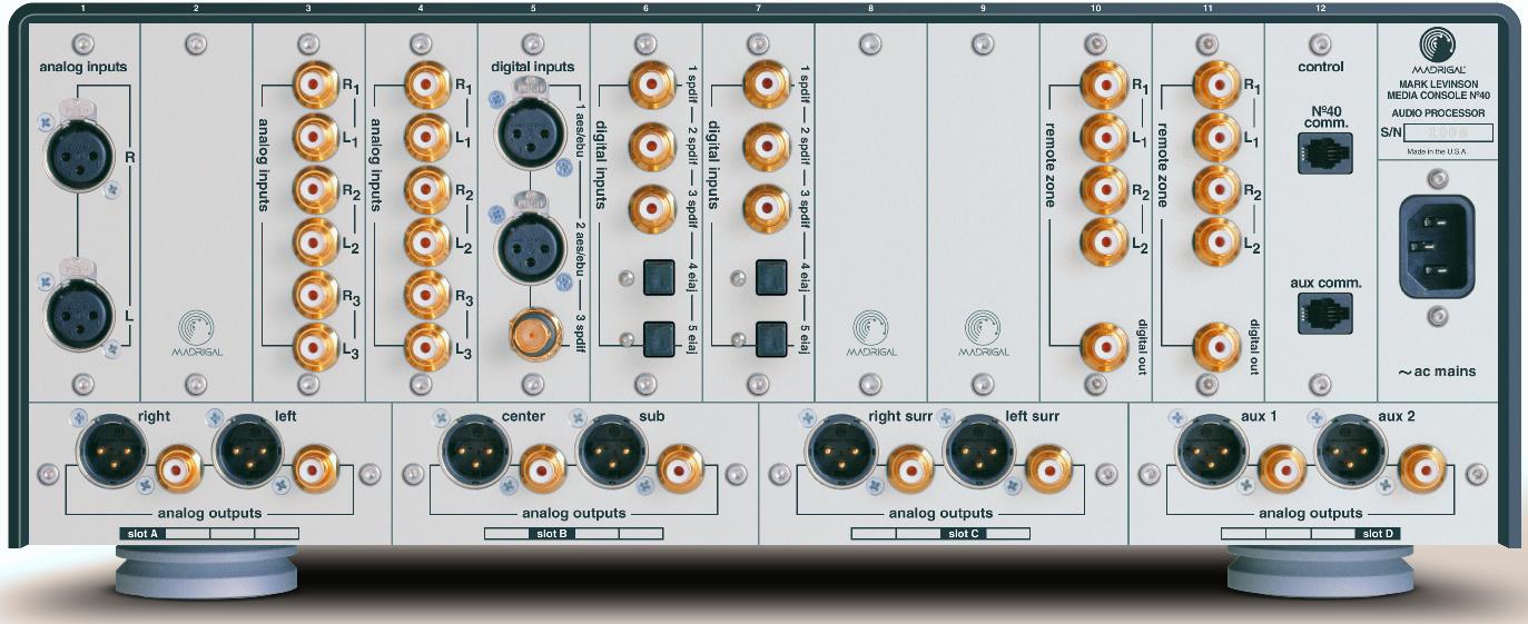
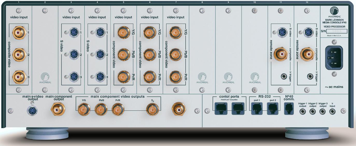
Here are the rear panels of the audio
processor (top photo) and the video processor (lower photo). You can click
on the photos to see larger, more detailed versions.


As delivered, the audio processor has numerous
filled card slots as well as three empty card slots for additional future
upgrades. Some of the cards include:
● A pair of two-channel balanced analog inputs.
● Three pairs of single-ended analog inputs (there are 2 cards with this
configuration).
● Two AES/EBU connections and one S/PDIF connection via a BNC connector.
Digital audio via three RCA and two Toslink inputs.
● HDMI inputs and outputs.
● A pair of single ended analog outputs and a digital output (there are 2
cards with this configuration: one for each of two remote zones).
Generally speaking, there is no fixed mapping of a card to any given slot. A
card simply registers the I/Os it provides for the slot its gets placed in.
ML does, however, have a default configuration that they offer where the
cards occupy fixed slot locations.
The audio and video processors communicate with each other through a custom
interface. The hookup for this interface is provided on yet another card.
There is a second connector on this card which is unused at this time. The
four SHARC DSP chips which crunch through the audio data are housed on this
card.
The cards which are oriented horizontally are located at the bottom of the
panel. These slots are named with letters instead of numerals. A pair of
balanced and single-ended analog outputs is located on a total of four
cards. These cards also provide digital to analog conversion and volume
control for their respective channels. Presumably the DACs can be changed by
swapping out these cards.
The video processor provides an assortment of analog video inputs and
outputs. The varieties of connectors that it offers are: Composite, S-Video,
and Component. There is one card offering three composite video inputs. Two
cards each provide three S-Video inputs. Three cards each offer a component
video input using BNC connectors. The two remote zones offer only composite
and S-Video outputs.
The video output for the main zone is offered through composite, S-Video, and
component connectors. The component connectors serve double duty, as they can
be configured to output RGB plus sync – there is an additional connector for
sync. A monitor output provides hookup with an external display device. I
connected this output to an external LCD which provided a better viewing
angle than the front LCD from my listening location.
Go to Part III.