Introduction
When we shop for a projector, one of the specifications
that we really want to be aware of is the Contrast Ratio (CR). In
general, we know that it is the relationship between the black and white
levels that a projector can show.
Well, it is a little more complicated than that, and this
article is designed to help you understand all the facets of the
contrast ratio, and what it all means for your home theater
enjoyment.
Background and
Nomenclature
Gamma is a basic, and very important
factor in images and contrast ratios. It
is the relationship between input voltage and the output light intensity,
and describes the non-linearity of intensity reproduction. Most
measurements use IRE values to represent
the input. In other words, you might send an IRE value of 30 (an input
voltage) to the projector to see what it will actually output
(brightness). I use X% stim (stimulus) instead of IRE, because IRE is
based on analog values. There can also be a 0 IRE or 7.5 IRE base value
for black, so it (IRE) is somewhat ambiguous when
discussing levels in sources.
Theoretically, the perfect gamma for a system from light
entering a camera, to the display, then reaching our eyes, would be 1, since this would mean
we were seeing the same ratios as the camera was receiving. Our current
system was mostly built around CRTs which have inherent gammas
approximately in the range of 2.2 to 2.5, and our eyes are also non-linear
in much the same way.
Therefore, gamma correction needed to be applied
to the sources to get to an approximate final gamma of 1. It should be
noted that gammas multiply and this would imply that reaching 1 would
require a source gamma in the range of 0.4 to 0.45. However, studies in
the past have shown an advantage to gamma totals of slightly higher than
1 in dimly lit surround environments often used for watching television.
Current sources are commonly encoded around the 0.5 range with final gammas
in the 1.0 to 1.25 range after taking gamma in displays into account.
Encoding sources with gammas less than 1 is actually useful for spreading
the information well for our eyes with a limited number of source bits
in digital encodings.
Non-CRT displays (e.g., DLP, LCoS, and LCD
projectors) need to emulate gammas like those of CRTs in order to correct
for the gammas in the sources they are fed. This is done with electronic
gamma correction using the digital video processor in the display
electronics to achieve gammas that are generally in the 2.2 to 2.5 range
(and are often within the control of the user). The exact gammas used
can have an impact on both contrast perception and shadow detail.
Specific advantages and disadvantages of pushing gamma toward one extreme
or the other, or modifying certain sections of a gamma curve, can vary by
scene makeup.
So, for example, in the diagram below, a
theoretically perfect video system would have a total gamma (source and
display) of 1 (red line). Gammas of less than 1 are above the red line
(except at the endpoints), while gammas greater than 1 are below the red
line (except at the endpoints). Or put another way, at the midpoint of
Input Voltage, lower gammas have higher Brightness (light intensity in
this case), and higher gammas have
lower Brightness (higher gammas have the midpoint pulled down to a
dimmer level).
For an example CRT display
that inherently has a gamma of 2.5 (blue line in the graph below), those desiring a lower gamma could
apply a gamma correction (green line) to move the display's final gamma close to 2.2
(black line). With
a source encoded with a gamma of 0.5, this would result in a final total gamma
for source and display of 1.1, while leaving this CRT at 2.5 would result
in a final total gamma of 1.25.
Note that the gamma lines in the
graph above are hand drawn approximations and just for illustration
purposes. Below is shown an actual graph of gamma 2.5.
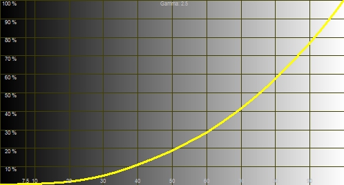
Consider a test image like the following:

Copyright Joe Kane Productions
The position of the vertical dots at each darker end
represents 0%stim (stimulus), and the position of the vertical dots at each
brighter end represents 100%stim. In this case, the gray bar in the
center, marked by the vertical dots, is 50%stim or 50% stimulus. This
does not result in 50% light output because
display gammas should be higher than 1 for our current video sources,
as explained above. With standard levels, 50%stim will result in light
intensity in the range of 18-26% of the light intensity of
100%stim. For the 20%stim bar, four in on the dark end, the correct
light intensity is in the range of 3-5% of
the light intensity for 100%stim.
Those light intensity levels being lower than their
stimulation amounts increase the importance of high contrast ratios in
order to maintain good separations between them and 0%stim (or video
black), as well as to keep bright areas in images from washing detail
out in lower %stim areas.
Note that I tend to use ftL as an abbreviation for ft-lamberts, or an indication of
the brightness of an image in the number of lumens reflected from a screen per
square foot. I may also use cd/m2 for candela per meter squared. The
conversion factors are 1 ftL = 3.426 cd/m2, and 1 cd/m2 = 0.2919 ftLs.
Types of Contrast
Ratio
Contrast Ratio (CR) is basically a ratio between
any two brightness levels, but the CR that we are most interested in is
the ratio of brightness between 0%stim and 100%stim. However, there are
various ways it can be measured. For instance, the ANSI CR is the ratio
between the averages (or sums) of eight 100%stim boxes in a 4x4
checkerboard and the averages (or sums) of eight 0%stim boxes in that
same checkerboard. I've included two examples of the ANSI checkerboard
here. The first one illustrates a poor CR, where the dark boxes are
gray (or dark gray) rather than the black that
they should be. The second one illustrates a good CR, where the dark
boxes should look black.


Copyright Ovation Multimedia, Inc.
Contrast ratio doesn't have to be a ratio between white
and black, it can be between two other levels (like white and one level
above black), but it is most common for it to be used for the ratio of
luminance between white and black for display devices.
In the
past it has generally been accepted that there were two valid contrast
ratios for a display, ANSI CR and On/Off CR (although many people
disparaged On/Off CR without understanding its importance, and some
still do). On/Off CR has also been called Sequential CR by some. With
the advent of dynamic systems like dynamic bulbs and dynamic irises, I
like to break out On/Off CR into two categories, Static On/Off CR and
Dynamic On/Off CR, for certain discussions. The dynamic one is what
would usually be published as the On/Off CR for a projector with a
dynamic system, but I also like to discuss the Static On/Off CR, which I
define as the On/Off CR without the bulb changing brightness or the
irises changing position based on the current image content. A projector
can have multiple Static On/Off CRs depending on things like the current
iris position though. For instance, as an iris closes down, the Static
On/Off CR will generally increase, which means that the ratio between
the white level and the black level generally gets better as an iris is
closed. This isn't always the case, but is true in general.
I and
others also like to use the term Simultaneous CR to describe the
contrast ratio in a single image. Some use the term Intra-scene CR, but
since scenes can consist of multiple frames, I prefer to use
Simultaneous CR. The ANSI CR test where a single image is used to
measure contrast ratio is an example of Simultaneous CR (although when
two checkerboards are used, so that measuring equipment doesn't need to
be moved, it is really an estimation of a Simultaneous CR). However,
ANSI CR is just one example, and any display has many (billions+) of
simultaneous CRs because there are billions upon billions of images that
it can display. I know of no formal definition for Simultaneous CR such
as whether it should be measured with the average of the brightest spots
divided by the darkest spots, or the peak spot divided by the darkest
spot, etc., so this is more of a concept.
On/Off CR basically
tells us the black floor from the projector for any white level, while
the ANSI CR gives us an indication of the washout effect by giving us
the CR for a checkerboard. Just like with any spec or test, neither one
of them tells us everything we need to know about a projector. While
each tells us how a display does in those tests, they only give us a
good indication of how the projector will perform with real images as
far as black levels. Real world content rarely contains any of the test
patterns used for many things with displays, like those used for color
calibration, convergence, geometry, contrast ratio, etc., but test
patterns can be very useful for characterizing and/or setting up a
display, as the patterns used for CR are.
In this case, I
consider ANSI CR as being toward one of the spectrum and On/Off CR at
the other end, which is a good way to give the best indication of the
whole range with only two specs.
These two specs can give us more information than might be
obvious at first glance. For instance, the On/Off CR is only for
100%stim images to 0%stim images, and it may look like it doesn't tell
us anything about 50%stim images to 0%stim images, which a person may
feel they are more interested in. When combined with the gamma, it does
provide us with information about those though.
The contrast calculator located at http://home1.gte.net/res18h39/contrast.htm does a
great job of estimating simultaneous contrast ratios from different
levels above video black to video black. I encourage readers who want to
see the effects of different On/Off and ANSI contrast ratios to try it
out. This calculator uses a zero base for IRE and so matches up with the
%stim values I use. If we set the values in the calculator to 8000:1
On/Off CR, 100:1 ANSI CR, and a 2.5 gamma for projector A, 2000:1 On/Off
CR, 500:1 ANSI CR, and a 2.5 gamma for projector B, along with room gain
of 0.01 and with 100% of the screen area covered by the checkerboard, we
can see that the estimates for the simultaneous contrast ratios for a
checkerboard of 50%stim and 0%stim are 64:1 for projector A and 111:1
for projector B. In this case, the projector with the higher ANSI CR has
the higher estimated simultaneous CR for that image. However, if we look
at the 20%stim row, we see that projector A leads in estimated
simultaneous CR with 49:1 to 40:1. If we then change the % of screen
area covered by the checkerboard to 20% (so that 10% of the screen is
illuminated by the brighter rectangles), we can see that projector A now
leads in estimated simultaneous CR with 272:1 against 260:1.
In
that calculator, one thing that can be difficult to pick is the room
gain (reflected light). I don't have exact values, but my best estimates
are that some of the worst rooms for reflections (bright white walls)
would result in values close to 0.05, and some of the best rooms for
reflections (mostly black velvet everywhere) would result in values
close to 0.001.
Images that are in between On/Off CR and ANSI CR
as far as image makeup (which is the vast majority of real images) will
generally have simultaneous CRs that are between the numbers for those
two. For instance, a Sharp XV-Z12000 which can have an ANSI CR of about
500:1 and On/Off CR of about 4000:1, can have a ratio of 2000:1 between
the brightest parts of an image and the dimmest parts with the right
image (e.g., small white area on large video black
background).
One thing to be careful of is in comparing
simultaneous CRs between two displays, since there are so many
simultaneous CRs for each display. For instance, as we saw in the
example above, with one display having much higher On/Off CR and lower
ANSI CR than another projector, each would be higher in simultaneous CR
compared to the other in some images and lower in others. So, neither
one could be said to have higher simultaneous CR, since it would depend
on the particular image chosen.
In my projector reviews, I will
be measuring On/Off CR and ANSI CR. The manufacturer's specifications
are just there as guidelines, and I want to be clear that it is actual
results that I am concerned with.
I should also mention that the
current article is mostly for front projection in rooms with enough
light control that the screen cannot be seen when the projector is off.
That is, I will mostly be discussing the CRs from the projectors. When
other lights are on in a room, or light is coming into a room and
hitting the screen, more lumens are generally the best way to maintain
high CR off the screen, and the CRs from the projector matter less.
However, this depends largely on how much light is hitting the screen,
as a very small amount could be negligible compared to the absolute
black level of a particular projector. Even single LEDs on the front
panel of DVD players and receivers can light up a projection screen if
they are pointed at it, but blocks of LEDs pointed toward the side in a
room with black walls can light up the screen less than the absolute
black level of a projector with 20,000:1 On/Off CR and a normal white
level. So, when people talk about LEDs killing On/Off CR, please keep in
mind that it depends on the room and the direction they are pointed, as
well as how bright they are.
Go
to Part II.