|
|||||||||
|
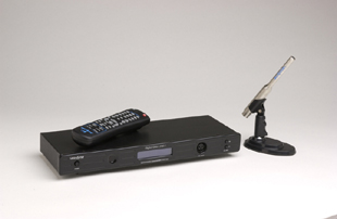
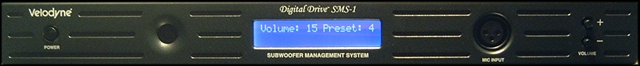
Introduction While there was great convenience in having all this functionality in the one box, Velodyne recognized that many of the unique design features of the Digital Drive system (excluding the digital servo), could be extracted and released as a standalone product, enabling owners of a wide range of other subwoofer makes and models to benefit from DSP (Digital Signal Processing) technology without having to invest in a whole new subwoofer. Most subwoofers suffer from problems caused by the room into which their subwoofer is installed. The laws of physics dictate that the room will tend to emphasize some frequencies compared to others due to a combination of the effects of boundary gain, room gain, and room modes. Everyone's room is different, and it is a sad fact of life that the bigger and better the subwoofer you use, the worse the problems can seem. Historically, you could fix some of the issues by engaging the services of a professional audio calibrator using expensive instrumentation to optimize the placement of the subwoofer(s) and/or employ some serious room treatments. Unfortunately, these seldom proved totally acceptable or effective, due to aesthetic or practical constraints, meaning that sub-optimal performance was all too often the norm. DIY attempts without proper instrumentation were always liable to be even more hit-or-miss. With the advent of digital equalization - while it is still important to find a good position for a subwoofer - it is now possible to compensate to a large extent for less-than-ideal subwoofer placements. Some dedicated DIY enthusiasts have already discovered and used a number of discrete tools to achieve an equalized in-room response, but the lack of integration makes the process time-consuming and laborious. The newly released Velodyne SMS-1 now offers this capability to the more mainstream subwoofer owner in a user-friendly, integrated package. The Design The SMS-1 consists of a slim black box that can be placed on any spare shelf of your equipment stand. It is also supplied with optional rack-mount ears, allowing installation in a standard 19" rack. Front panel controls consist of the on/off switch and buttons for volume. A small illuminated LCD display panel provides visual feedback for the main operating functions, and there is an XLR socket that allows the supplied measurement microphone to be conveniently connected.
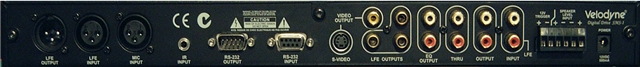
On the rear panel, working from right to left, there is a 12V DC power socket to which you connect the supplied wall wart power supply. A small terminal block provides high-level connections from your speaker terminals if you choose this method of connection, as well as a 12V trigger input. Next is a pair of Input RCA jacks for connecting to the input signal. One of these can be connected to the receiver or SSP's sub-output jack (mono), or the pair can alternatively connect to the stereo L&R outputs from a preamp. The Output RCA jacks may optionally be used to supply a stereo signal back to the power amplifier to drive the main L&R speakers. This is subject to a fixed high-pass crossover filter within the SMS-1 at 80 Hz with a 6 dB/octave slope using a conventional analog crossover circuit. The Thru RCA sockets allow the unaltered input signal to be passed to another device downstream. An example might be another daisy-chained SMS-1 controlling a second sub. The EQ Output RCA sockets are where the sine-sweep test signal is generated and should be connected to a spare analog input on the receiver or SSP. Next come three LFE Output RCA sockets that can be used to connect up to three subwoofers. Each produces an identical signal. Composite and S-Video TV outputs are provided, one of which should be connected to a TV or other display device for visualizing the EQ curves and accessing the menu structure. There is a 9-pin RS232 input socket to allow serial control by Crestron/AMX-type universal remote controls as well as the ability to upload software upgrades using a PC. The 9-pin RS232 output socket allows a second daisy-chained SMS-1 to be controlled as a slave by the first (master) unit. An external IR remote sensor may optionally be connected via a 3.5mm jack. Finally, there are three XLR jacks, allowing an alternate place to connect the microphone, another LFE input, and an LFE output. Internally, all the inputs are summed to create a single channel (mono) signal. This is converted to digital using a 20-bit A/D converter. The heart of the device is a Texas Instruments TMS320LF2407 DSP chip running proprietary Velodyne software, hand-coded in assembler language for speed. This takes the digital signal, performs all the sweep-generation, digital filtering, phase control and video-display functions, generating a modified mono digital signal which is converted back to analog and fed to the three RCA and one XLR LFE outputs from the device. Software is stored in flash memory and can be updated via the RS232 input socket using a PC and mouse extension cable. Software upgrades can be downloaded from the Velodyne website and arrive in a self-extracting *.zip file. All parameters are retained in non-volatile memory.
|
|||||||||


Magazine Publishing Solutions by