Introduction to the The Inner World of LCD TVs – Part II
As you probably know well by now, LCD TVs are far and away the most popular type of flat-panel television available today. But exactly how they work is a mystery to most, even technically inclined folks within the industry. So I decided to provide a clear and comprehensive explanation of the inner workings of LCD TVs—no easy task, I can assure you!
In Part I, I explained what liquid-crystal material is and how it is electrically manipulated to let more or less light from the TV’s backlight pass through each red, green, and blue subpixel in order to form a full-color image on the screen. However, while the concepts presented there form the foundation of how liquid-crystal displays work, they aren’t sufficient to make a high-quality television. That requires some modifications, which I’ll discuss in Part II.
If you haven’t read Part I yet, I strongly recommend that you do before continuing with Part II. Part I is located HERE.
Recapitulation
As you’ll recall from Part I, the basic idea of an LCD is that nematic liquid-crystal molecules naturally align themselves with each other and with grooves in the director plates, or substrates, that form the boundaries of the liquid-crystal layer. The grooves in the front plate are perpendicular to the grooves in the back plate, causing the liquid-crystal molecules to form spiral structures, not unlike DNA molecules, between them.
Just outside the director plates are polarization plates, also at right angles to each other. Light from the backlight is polarized by the inner polarization plate, then that polarization follows the twist in the liquid-crystal molecules and emerges through the outer polarization plate. But when a voltage is applied to electrodes on either side of the LC material, an electric field is created, and the orientation of the LC molecules aligns with the field. As a result, the polarization of the light passing through the LC material is not entirely realigned with the outer polarization plate, which then blocks it. The stronger the field, the less light gets through.
The design I described in Part I, which is called twisted nematic or TN, is insufficient to make a television with acceptable picture quality. In particular, the viewing angle is narrow and asymmetrical, response time is slow, and color reproduction is poor. In the quest for better LCD TVs, two major approaches have emerged—IPS (in-plane switching) and VA (vertical alignment)—each with several variations.
In-Plane Switching
IPS panels are very similar to TN with one major difference—each subpixel has two TFTs (thin-film transistors) on the same surface as shown in Fig. 1, so the electric field used to realign the liquid-crystal molecules is parallel to the substrates rather than perpendicular to them as in TN panels. As a result, the liquid-crystal molecules remain parallel to the plane of the plates, which is why this technique is called in-plane switching.
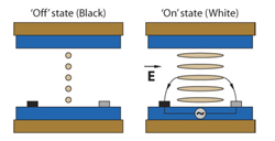 Fig. 1: In IPS panels, two transistors or electrodes are placed on the same substrate in each subpixel cell, creating an electric field that is parallel to the substrate. The stronger the field, the more light passes through the cell.
Another difference between IPS and TN is that, while the grooves in the director plates are perpendicular to each other, both polarization plates are aligned in the same direction. So when no electric field is present, very little light gets through the panel assembly. As the electric field grows stronger, the liquid-crystal molecules become less twisted, allowing more light to pass through the second polarizer plate.
Because there are two transistors on the same substrate for each subpixel, they take up more space than the transistors of TN panels, which reduces contrast and brightness. (IGZO transistors mitigate this problem; more about this technology shortly.) Plus, they are more expensive to manufacture. However, IPS panels exhibit fairly consistent color and contrast from a wide range of viewing angles.
Hitachi developed IPS in 1996, and has made some improvements since then. In particular, Super IPS (S-IPS) improves refresh rates, and Advanced Super IPS (AS-IPS) improves the contrast ratio. IPS Pro—sometimes called IPS Alpha—provides a wider color gamut and even better contrast. This technology was acquired by Panasonic in 2010 and is used in LCD TVs from Panasonic, Hitachi, and Toshiba.
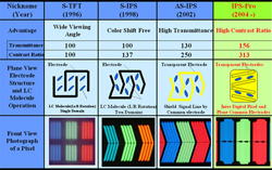 Fig. 2: Viewed from perpendicular to the panel, S-IPS and AS-IPS use chevron-shaped electrodes to improve transmittance. IPS Pro (aka IPS Alpha) also uses angled electrodes within a more rectangular cell.
Meanwhile, LG has been developing its own variations of IPS since 2007. These include Horizontal IPS (H-IPS), which improves contrast by twisting the electrode plane layout, and Enhanced IPS (E-IPS), which widens the light aperture to allow the use of lower-power backlights as well as improving the diagonal viewing angle and reducing the response time. H-IPS is used in LCD TVs from LG, Sony, Philips, and BenQ.
Vertical Alignment
The other type of LCD technology used in TVs is called vertical alignment (VA), which was originally developed by Fujitsu in 1996. As the name implies, the LCD molecules are aligned vertically—that is, perpendicular to the substrates. If no voltage is applied, light passes through the LCD material but is stopped by the perpendicular polarizer at the other end. As more voltage is applied, the molecules reorient themselves horizontally, and more light passes through the second polarizer.
VA panels are less expensive to manufacture than IPS because they have only one transistor per subpixel. However, they suffer from more image degradation when viewed from off axis. In addition, the degradation is not uniform from one side to the other—in one direction, the image looks lighter and washed out, while from the other direction, it looks darker. Also, the color changes depending on the direction from which you look at the panel. This is because from one direction, you are looking at the molecules from their side (which looks lighter), while in the other direction, you are looking at them end-on (which looks darker).
To address this problem, a variation called multi-domain vertical alignment (MVA) was developed by Fujitsu in 1998. In this technology, a small pyramidal bump is placed in each cell, and the LCD molecules align themselves with the sides of the pyramid. As a voltage is applied, the molecules flatten out in a radial pattern, becoming more horizontal and allowing more light to pass through the second polarizer.
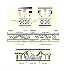 Fig.3: With simple or mono-domain VA (left), viewers from one side see a lighter image, while viewers from the other side see a darker image. With multi-domain VA (right), viewers see the same image from any direction.
With MVA, the image quality still degrades as you move off axis, but the degradation is the same no matter where you are in relation to the screen. This is because you are always looking at some of the molecules from their sides and other molecules end-on.
Variations of MVA include patterned vertical alignment (PVA), which was developed by Samsung, and Advanced Super View (ASV) developed by Sharp. All share the basic characteristics of deeper blacks but more off-axis image degradation than IPS.
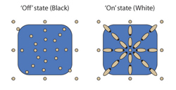 Fig.4: In Sharp’s ASV technology, also called Continuous Pinwheel Alignment (CPA), the liquid-crystal molecules form a circular pattern when an electric field is applied.
Let There Be Backlight
Regardless of the type of LCD technology, all LCD TVs must include a backlight located behind the LCD panel. White light from the backlight passes through the liquid-crystal material, and each red, green, or blue subpixel blocks more or less of it from emerging and reaching viewers’ eyes based on the electric field applied to that subpixel. The more light that emerges, the brighter that subpixel appears on the screen.
LCD TVs used to employ CCFL (cold-cathode fluorescent) backlights, which consisted of several horizontally oriented fluorescent tubes, much like the tubes found in office light fixtures, only smaller. A diffuser placed in front of the tubes dispersed the light, distributing it much more evenly across the entire back of the LCD panel.
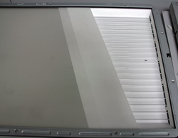 Fig.5: LCD TVs originally used thin fluorescent tubes as backlights.
These days, virtually all LCD TVs use LEDs (light-emitting diodes) as the backlight, because they use less power and are more environmentally friendly, since they contain no mercury. In addition, LEDs offer a greater degree of dynamic control—they can be quickly dimmed and brightened to enhance the apparent contrast of the image.
In most modern LCD TVs, the LEDs are mounted along one or more edges of the panel; this is called edgelighting. The LEDs can be placed along the top, bottom, left, and/or right sides. Special light-guide panels diffuse the light and bend it to pass through the LCD panel.
A few LCD TVs have LEDs mounted in an array directly behind the LCD panel; this is called direct or full-array backlighting. A diffuser is still required to spread the light evenly across the entire back surface of the panel, but it needn’t bend the light to pass through the panel.
 Fig.6: In LED-backlit designs, an array of LEDs is placed behind the LCD panel.
Direct or full-array LED backlighting offers several distinct advantages over edgelighting. For example, the illumination is more uniform across the screen, which is particularly evident in dark scenes.
Another advantage of direct LED backlighting over edgelighting is the possibility of a feature called local dimming. The TV’s processor analyzes the image and dims the LEDs behind the dark areas while brightening the LEDs behind the bright regions. In essence, the LEDs form a low-resolution, monochrome image that corresponds to the high-res, full-color image on the screen, as shown in Fig. 7 below. This greatly increases the perceived contrast in the image, though it’s not without its own problems, which I’ll describe shortly.
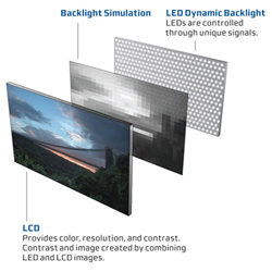 Fig.7: In LCD TVs with full-array backlighting and local dimming, the LEDs behind the LCD panel form a low-resolution, black-and-white version of the image on the screen, darkening the dark parts and brightening the bright parts.
So why don’t more LCD TVs use LED backlighting? For one thing, it means the TV can’t be made as thin as it can with LED edgelighting—and thin seems to be a top priority with consumers these days. Also, LED backlighting with local dimming is more expensive to implement, so it’s normally found only in high-end sets. (Vizio recently bucked this trend by announcing that its entire 2014 line of LCD TVs will use LED backlighting with local dimming.)
A growing number of companies are introducing low-cost LCD TVs with backlighting instead of edgelighting. However, these sets have no local dimming, and there are fewer LEDs than in sets with local dimming. To distinguish them from full-array local-dimming (FALD) sets, the backlight technology is often referred to as “direct backlighting,” which still has the advantage of more uniform screen illumination than edgelighting.
Perennial Problems
LCD TVs have always suffered from several problems with picture quality, including low contrast, high black level, motion blur, poor uniformity, and narrow viewing angles. Each of these problems has been addressed in various ways, though some of the solutions also introduce problems of their own.
Contrast and black level are closely related. Virtually all LCD TVs can pump out lots of light at the bright end, so the lower the black level, the greater the contrast. However, achieving a low black level is very difficult, because the LCD material isn’t 100% effective at blocking light from the backlight—some light always gets through.
One way to lower the black level is by using a so-called black-matrix design, in which the subpixels are separated by opaque black lines (see Fig. 8). Another technique is black-frame insertion, which, as the name implies, inserts black frames between the actual video frames. (This also helps reduce motion blur; more in a moment.) Both of these solutions also lower the maximum amount of light at the high end, which is called the peak white level, but most LCD TVs have plenty of light to spare, so this isn’t really too much of a problem.
 Fig.8: A black-matrix LCD panel has opaque black lines separating the subpixels.
Full-array backlighting with local dimming lowers the black level considerably and increases the overall contrast in actual images. However, the number of LEDs is always much less than the number of pixels, and they are controlled in groups or zones, not individually. As a result, local dimming has trouble with very small areas of brightness or darkness. For example, tiny bright spots, such as stars in space, often look like they have halos around them because the LEDs behind the stars also brighten the space around them.
Many LED-edgelit sets offer something akin to local dimming—for example, sets with edge illumination can turn off the LEDs adjacent to the black letterbox bars in widescreen movies to make these bars appear much darker than they otherwise would be. Many manufacturers call this “local dimming,” but it isn’t really the same, and it’s not nearly as effective as true local dimming with full-array backlighting.
Another LCD bugaboo is motion blur—that is, objects in moderate to fast motion look blurry and can leave ghostly trails behind them. Of course, some blurriness is due to the fact that video consists of a series of still images taken at a certain frame rate, and all moving objects look blurry to one degree or another.
But LCDs exaggerate this effect mostly because liquid-crystal molecules take some time to shift their alignment from one frame to the next. Also, the LC molecules are still switching while the video frame is being displayed. This transition from one alignment to another is known as response time, one of the most widely recognized specifications of LCD TVs.
Unfortunately, TV and panel manufacturers rarely disclose exactly how response time is measured—from black to white to black or gray to gray—and the time to transition from one gray level to another changes depending on the start and end levels. Surprisingly, the time it takes to transition from one gray level to another is often longer than the transition from full black to full white and then back to full black.
Although overall response times have decreased over the last 10 years or so, motion blur remains a problem for LCD TVs. To minimize this effect, NEC developed a compensating circuit in which the voltage applied at the beginning of each frame is higher than what is ultimately needed. This higher voltage accelerates the movement of the liquid-crystal molecules to their new position. For those subpixels that do not change from one frame to the next—which is a majority of them most of the time—the voltage is held constant, reducing the time required to charge and discharge all the capacitors.
Another way to compensate for motion blur is black-frame insertion, in which a black frame is inserted between video frames. This technique lets the LC molecules settle into their new orientation before you can see the subsequent video frame. A related technique is called backlight scanning, which turns off the backlight in sequential horizontal segments from the top of the screen to the bottom during the transition from one video frame to the next.
Probably the most effective technique to combat motion blur is frame interpolation, which is available only in LCD TVs with a refresh rate of 120 Hz or higher. As shown in Fig. 9 below, the TV’s video processor looks at two consecutive video frames, identifies objects in motion by the fact that they are in different locations from one frame to the next, and synthesizes (interpolates) one or more new frames to display between the incoming frames. Any objects in motion are placed in the new frames where they should be if those frames were actually present in the signal.
 Fig.9: When frame interpolation is turned on, the TV’s processor analyzes where moving objects are in each incoming frame and synthesizes new intervening frames with the moving objects placed where they would be if the scene had been captured at the higher frame rate.
Frame interpolation is quite effective at sharpening the detail of objects in motion. However, it also creates an artifact commonly called “the soap-opera effect,” because it makes the moving image look like it was shot on live video at a higher frame rate, just like a soap opera. This is especially apparent in movies that were originally shot at 24 frames per second. Many viewers object to the soap-opera effect far more than they dislike motion blur, so they turn off the frame-interpolation function in the TV.
Most LED edgelit TVs suffer from uneven screen illumination, which is particularly evident in dark scenes, such as those depicting outer space. This usually manifests as lighter and darker areas on the screen, often in the corners, and is often known as “flashlighting.”
Finally, we get to the bane of all LCD TVs, no matter what their illumination source is—limited viewing angles. As your viewing position moves off center with respect to the TV screen, black and dark gray levels on the screen appear to rise, brightness dips, and images consequently appear washed out. In addition, colors shift and lose saturation.
Basic TN LCD panels have very narrow viewing angles that are asymmetrical as well—the image degrades in one way when moving from side to side compared with moving up and down, which is why TN is not used in consumer TVs.
IPS and MVA technologies provide wider, more symmetrical viewing angles, but not nearly as wide as plasma or OLED (organic light-emitting diode) flat panels. In general, IPS offers wider viewing angles than MVA, but MVA typically provides lower black levels, at least when viewed on axis—that is, directly in front of the center of the screen.
 Fig.10: TN LCD panels exhibit very poor, asymmetrical off-axis performance compared with advanced LCD technology such as IPS.
Things like black level and motion blur can be improved with technologies such as local dimming, black-frame insertion, and frame interpolation, but I know of no solution that completely eliminates viewing-angle limits. As a result, LCD TVs are generally not recommended if you routinely have lots of people watching the TV or you watch it while lying on the floor. Also, LCD TVs don’t normally do well mounted high above the floor—say, over a fireplace—unless the mount can be tilted downward toward the viewing area.
A Bright Future
With OLED TVs becoming available—albeit at exorbitant cost—you might think that LCD TVs have reached the apex of their maturity. However, there are still a few advancements on the horizon that could extend the life of LCD technology for years to come.
Probably the most obvious advancement is the increase in pixel resolution from 1920×1080 to 3840×2160—a four-fold increase in the number of pixels from so-called Full HD to Ultra HD. Many manufacturers are jumping on the UHD bandwagon, offering LCD TVs with over 8 million pixels. The manufacturing process isn’t that much different than current panels, so companies are churning them out and selling them at a premium. (Surprisingly, that premium is decreasing much faster than the premium charged for LCD TVs when they were first introduced to compete with plasma TVs.)
Even so, the introduction of UHDTVs is premature, since there is very little content with native UHD resolution. Also, other aspects of UHD content have not yet been finalized, including dynamic range, color gamut, bit depth, and color subsampling. As a result, many UHDTVs purchased today will likely be unable to fully reproduce the UHD content of the future.
The biggest current advantage of UHDTVs is their ability to display 3D with Full HD resolution for each eye using passive-polarized glasses or no glasses at all. Passive-glasses flat panels cut the vertical resolution available for each eye in half, which is a problem when the panel starts with 1080 lines of vertical resolution. But with 2160 lines of total resolution, each eye gets 1080 lines.
Glasses-free or autostereoscopic 3D also reduces the resolution available for each eye, so UHD TVs are prime candidates for this technology. This is great news for companies such as StreamTV Networks and Dolby, which are on the verge of releasing glasses-free 3D for large-screen LCD UHDTVs.
Another advancement is quantum-dot backlighting, which is being developed by Nanosys, QD Vision, and other companies. As particles of certain semiconductor materials shrink to a size of around 2 to 10 nanometers in diameter—larger than a water molecule, smaller than a virus—they emit light in a very narrow band of wavelengths when bombarded with blue light. Why? Because particles that small exhibit quantum-mechanical effects—in this case, they absorb the energy of blue photons and release it again at a very specific wavelength.
The wavelength emitted by a quantum dot depends mostly on its size—larger dots emit red light, smaller dots emit green light, and so on. In fact, the emitted wavelength can be fine-tuned simply by changing the size of the particles, which can be accurately controlled in the manufacturing process.
In a quantum-dot backlight system, a thin film of material containing quantum dots is placed behind the LCD panel, or thin straws of material are placed along the edges of the screen. Instead of using white LEDs, this system uses blue LEDs. The dots in the film or straws are tuned to emit red and green light when blue light from the LEDs hits them, though some of the blue light passes through the material without being absorbed. All three colors combine to form white light, which then passes through the LCD layer like any other backlight.
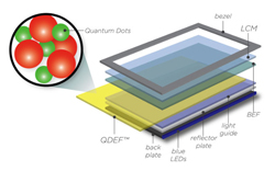 Fig.11: In QDEF (quantum-dot enhancement film) technology from Nanosys, red and green quantum dots are embedded within a thin film that is placed in front of an array of blue LEDs. The light from the red and green quantum dots combines with the light from the blue LEDs to form white light.
Quantum-dot backlighting can expand the color gamut of an LCD TV and make it brighter—as if LCD TVs needed to be brighter!—and more energy efficient. Sony introduced the first commercial LCD TV using quantum-dot backlighting from QD Vision at CES 2013, calling it Triluminos.
Yet another recent advancement is a new type of transistor. As we’ve seen, every subpixel in an LCD TV requires at least one transistor, which has traditionally been fashioned from amorphous silicon or low-temperature polysilicon. These transistors are limited in their size and transparency, which reduces the amount of light that can pass through each subpixel. They also need a certain amount of power and can’t be turned off entirely, so some light always leaks through even when a subpixel is supposed to be completely black. Finally, the transistors have a limited switching time, leading to motion blur.
A new type of transistor called IGZO (indium gallium zinc oxide) could improve the performance of LCD TVs and other types of displays that rely on these semiconductor devices. IGZO transistors can be made smaller than other types with greater transparency, so more light can get through the panel.
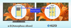 Fig.12: IGZO transistors can be made much smaller than amorphous silicon.
Other advantages include faster switching speeds for less motion blur, lower power consumption, and lower current leakage, resulting in deeper blacks. IGZO transistors have been in development since the mid-1980s, but Sharp is the first company to master the manufacturing process, and the company is now including this type of transistor in its higher-end sets.
LCD TVs are among the most successful consumer-electronics products of all time. What began as a high-end niche product is now the de facto standard for flat-panel TVs, with models available at every price level. The inner workings are pretty geeky, but I find the whole subject fascinating, and if you’ve made it to the end of this 2-part article, you obviously do too. May this knowledge serve you well in your quest for ever-greater understanding of video technology.
Many thanks to Pete Putman of ROAM Consulting LLC for his help with this article.


