Do It Yourself
Project #1 - The Audax A652 - July, 1996
By Ralph Calabria
![]()
 |
* Note: IF you would like to submit a
DIY project for
publication in Secrets, contact the DIY Associate Editor
- Introduction
- The diagram
- The drivers
- The crossover
- The enclosure (a.k.a. cabinet, box, shell, etc.)
- The front baffle
- Cabinet finishing (veneering, staining, topcoating)
- The grille
- Putting it all together
- The stands
- The sound
- The cost
- Tools
- Acknowledgments
- Bibliography
![]()
Introduction
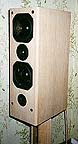
The Audax A652 is a kit that was developed by Vance Dickason, the author of the famous speaker-builder "Bible " The Loudspeaker Design Cookbook. The A652 is a vented design laid out in the classic D'Appolito configuration where the tweeter is sandwiched in between two mid-bass drivers. The advantages to this arrangement are a smooth vertical frequency response above and below the listening axis, increased sensitivity, and a greater SPL (i.e., these puppies can be played at 105 dB!). The 2-way design uses two Audax HM170CO 6.5" woofers and a TW025MO 1" textile dome tweeter. The crossover is a 4th order Linkwitz-Riley type at 2,800 Hz. This 4th order (24 dB/octave) slope is achieved by using a 3rd order network and the natural rolloff of the drivers. Sensitivity of the speaker clocks in at 90dB/w/m, and the nominal impedance is measured at 4 Ohms. Frequency response is 60 Hz - 20 kHz ± 2.2 dB with usable bass down to 37 Hz.
There are several parts that make up a loudspeaker. The editor has described them in his primer section on speakers found in Volume 1 Number 1, 1994. I will go into fair detail as to how I constructed each of these parts. Even though I did not design this project from scratch, there is a lot of associated information and techniques that anyone from the kit builder to the amateur designer can use in his or her DIY project. After all, that is what this is all about, right? We want to have fun, use our brains, tweak here and there, and maybe even save a little money (assuming we don't put a price on our precious time) by doing it ourselves.
If I may say, I am not a professional speaker builder. This is only my second attempt at speaker building; my first was several years ago, which was not considered in my eyes a success (Please, don't ask!). Anyway, after getting back into the "art" of this very satisfying hobby, I came across a vast amount of information on the Internet. With the help and guidance of many, this project can be considered more of a success than I'd ever hoped. It is my intention in submitting the first contribution to this new DIY section of Secrets of Home Theater and High Fidelity, to provide information, and share my experiences with others. The techniques that I used in this project should not be considered as the only way to do things, rather, just the way I thought was best for me. I hope this project sparks some ideas from you. Whether you are just getting started in this hobby or have built speaker projects before, you may find something of interest here.
![]()
The diagram
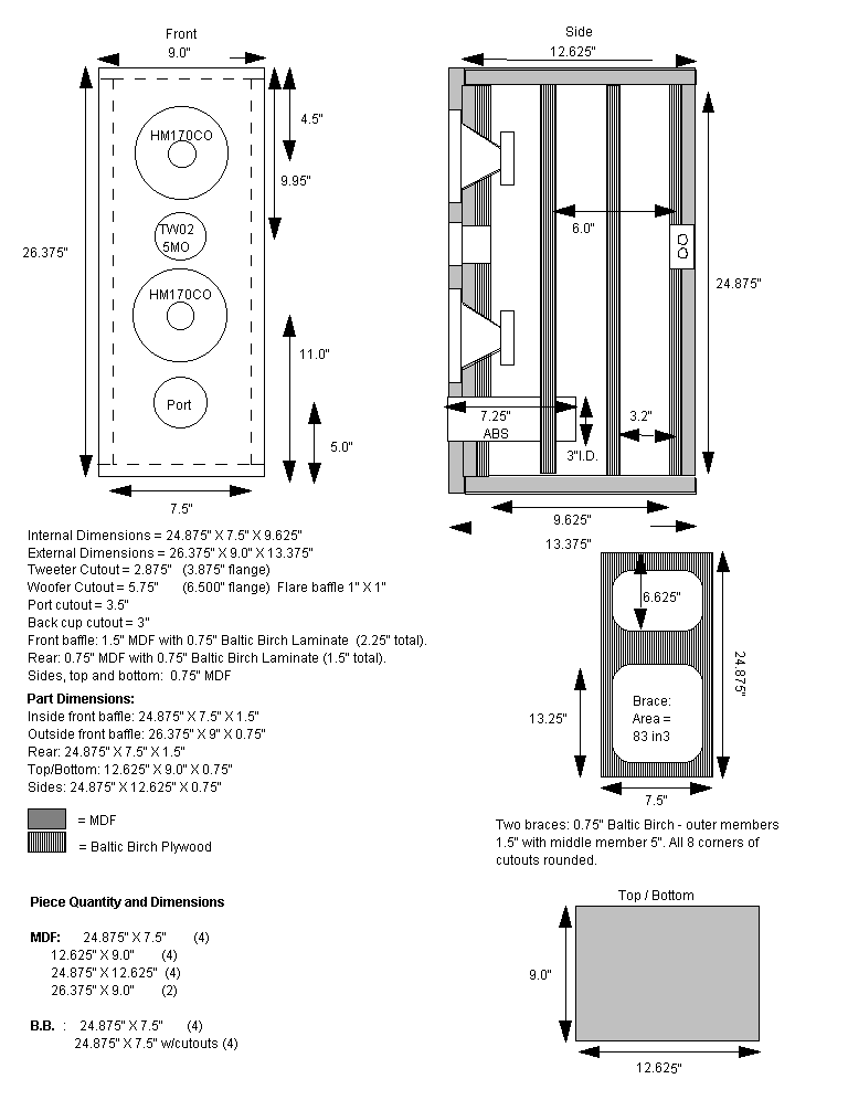
Here are my cabinet plans for the A652. The original plans may be found at Audax's web site located at: http://www.audax.com
![]()
The drivers
The HM170CO is a 6.5" woven carbon fiber woofer. This space-age material has been around for quite some time now and has become popular as a cone material for speaker drivers. Carbon fiber is noted for its stiff, rapid-response properties. The mid-bass is quick and tight on these drivers. For reference, here are the Thiele/Small parameters and various specs on the driver.
Voice coil diameter: 30 mm Impedance: 8 Ohms Freq. response: 55-11,000 Hz Magnet weight: 20 oz. Fs: 42 Hz SPL (1W/1m) 90 dB Vas (1 cu.ft.) 1.08 Qms: 4.16 Qes: 0.35 Qts: 0.32 Xmax: 3 mm
The TW025MO is a 1" textile soft dome tweeter. The sound? Well, it's very smooth, not brassy or bright like some metal dome tweeters can sound. But this comes into a gray area. Some people like the up-front sound of metal domes (e.g., aluminum, titanium, etc.). It's all a matter of taste. For me, the soft domes are less fatiguing than the metal domes; that is, listening to them for considerable lengths of time does not strain the ear drum. Here are the tweets vitals.
Voice coil diameter: 25mm Impedance: 8 Ohms Magnet weight: 10 oz. Fs: 900 Hz SPL (1W/1m) 92 dB Xmax: 0.3 mm DC resistance 5.8 Ohms Voice coil Inductance 11 µH
![]()
The crossover
Here is the crossover (xover) schematic for the Audax A652.
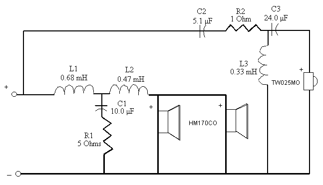
Diagram of crossover copyright Audax.
In the crossover (xover) network, there is the tweeter (or high pass) xover and a woofer (or low pass) xover. There are three electronic components in the xover: the resistor, the capacitor, and the inductor. For an explanation of these parts, I refer you to the editor's primer again. The tweeter and woofer xovers were assembled on separate boards. This was done for a couple of reasons. The inductors can interact with each other if they are placed too close together, especially if they are aligned in the same plane. In the case of the woofer xover where there are two inductors, the inductors are laid in a perpendicular plane to one another and on opposite sides of the xover board to avoid this interaction. Also, the inductors are large, so fitting both xovers on one board would make it difficult to install a larger xover in the cabinet through the woofer cutout.
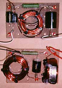
I used quality xover parts: 14 gauge air core inductors, metallized polypropylene caps, and Ohmite ceramic core resistors. The board used to assemble the xovers was 1/4" pegboard which was cut into 4" X 6" pieces. The pegboard is a good choice because it has holes that are spaced about 1" apart and serve as both a guide to laying out the xover parts and a way to secure the xover parts to the board. I positioned the inductors where they were to be installed on the pegboard. Four tie wraps/inductor were place up through the holes of the pegboard so they could be tightened around the inductor. I removed the inductor and covered the bottom of it with Liquid Nails glue and re-positioned it on the xover board. I then closed the tie wraps around the inductor tightly. I used the crimp- and-solder method to connect the xover parts. First I laid the parts on the board where they were to be connected. Then I used uninsulated ring crimp connectors to crimp all the components together according to the schematic. The crimping was done with a crimping tool that is available at most hardware stores. Once all of the crimps were made, and making sure the crimps were a good solid connection (nothing should move when you pull on them), I secured the xover to the pegboard. I placed the hole of each of the ring crimps over a hole in the pegboard. I sent a #10/32 brass flat machine head screw up through the hole and secured it with a brass hex nut. I tightened the nut until the screw head was countersunk flush with the pegboard on the other side. This allowed for a flush mount of the xover in the cabinet. I then "painted" the screw threads with nail polish (I prefer shocking pink!) so the vibrations from the speaker would not loosen the nuts. Once the xover was secured to the pegboard, I soldered each connection using silver solder which DID NOT contain an acid flux. This is important when dealing with electronic parts. Care should be taken not to overheat the connections. Too much heat can cook the capacitors. I used a 40 watt soldering iron for best results. Silver solder, which usually also contains lead and tin, has a fairly low melting temperature. Since the components were connected by crimping the components together, "tinning" the parts was not a necessity. Tinning is a term which means putting solder on the xover leads before the parts are soldered together. This avoids a cold weld, which can come apart later if pressure is put on the connection. I heated the crimp connector at the point of the crimp, with the solder touching the crimp as well (but not the iron) until the solder began to flow. I removed the iron and applied enough solder to completely fill the inside of the crimp barrel. Once everything cooled, I bonded the xover parts to the pegboard using 100% silicone glue (this prevents buzzing from vibration inside the cabinet when music is played). Once the glue had set, I removed the tie wraps that I put on the inductors earlier. A lot of these tips can be found in a nice little booklet offered by North Creek Music Systems (NCMS) Wiring Guide. Here is a picture of the finished xover boards (xovers).
*NOTE: When crimping the components together, don't forget to crimp all wires associated with that crimp. That means crimp the xover components AND any wires that are connected to that point (wires going to drivers or back terminal cup). This will make things easier when connecting the xover to the back plate and drivers later. This technique also eliminates extra connections that can degrade the sound of the speaker. The rule of thumb is: "The less (and shorter) connections, the better." For example, when the inductor wire leads call for connecting them to the terminal cup, they should be connected directly to the terminal cup and not to another soldered connection, and then to the terminal cup. Every additional connection has the potential to degrade the sound. For this very reason, printed circuit boards (PCB) are not recommended for assembling xover networks. That does it for the xover for now until its time to put them in the cabinet.....which leads us to the next topic in the project.
![]()
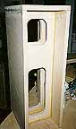
The enclosure (a.k.a. cabinet, box, shell, etc.)
IMHO, this portion of the project is by far the most time consuming and labor intensive. It is also the most fun. And that's one of the reasons why we're doing this, right. Again, my hat comes off to NCMS for offering another booklet entitled Cabinet Handbook. It is a valuable tool in building a better cabinet. Many of their suggestions were incorporated in the cabinet design.
This is where there is a big difference between my project and the original design. V. Dickason used 3/4" MDF for the top, bottom, sides, and back, and 1" MDF for the front. He added one 3/4" MDF cross brace between the bottom woofer and tweeter, with cutouts in the brace so that all crossbracing widths were 3/4" all across. Dickason's external dimensions were 26 3/8"H x 9"W x 10.5"D with an internal volume of approximately 1 ft3.
My enclosure was made from 3/4" medium density fiberboard (MDF) and Baltic birch plywood. I would have preferred to use 1" MDF, but I couldn't find it at the time I was ready to start the cabinets. The 2 1/4" thick front baffle was made by laminating two pieces of 3/4" MDF and one piece of 3/4" Baltic birch plywood. The MDF pieces were glued together using standard yellow carpenter's glue. The Baltic birch (BB) was laminated to the MDF using soft "Tacky Glue" found in a local craft store. The soft tacky glue was used between the BB and MDF because it provides a better damping layer than the yellow glue. The outside piece of MDF was cut the dimensions of the outside of the cabinet so that this piece could be mounted flush with the sides, top and bottom. This was done because the front sides were routed to reduce deflection (see Cabinet finishing section for details). The inside pieces of MDF and BB plywood were cut the dimensions of the inside area of the cabinet such that they would slide into the cabinet once framed out. The 1.5" thick back panel was made by laminating a 3/4" MDF panel with 3/4" BB plywood. Again, the soft glue was used in between the panels. The sides, top and bottom panels were 3/4" MDF. Two 3/4" BB braces were used. The braces were arranged vertically in the cabinet to brace the top, bottom and sides since the back and front were sufficiently stiff because of their extra thickness. (Remember, stiffness is proportional to the cube of the panel thickness, so, if you double the thickness, the panel becomes 8 times as stiff). The braces were 1 1/2" wide all around with a 5" cross piece positioned about 1/3 down from the side walls. This affords a figure 8 configuration (for a picture, see braces). I used a jigsaw to cut the figure 8 out of the braces. According to the NCMS handbook, the braces were placed 1/3 and 5/8 from the center of the nearest unbraced area, starting from the back. This irregular orientation prevents any one resonant frequency from dominating in the cabinet. The additional thickness of the front and rear panels and the added extra brace necessitated a change in the overall dimensions of the cabinet from the original design. Keep in mind that the overall internal volume was unchanged, about 1 ft3. The external dimensions of my enclosure were 26 3/8"H x 9"W x 13 3/8"D. Note that the internal depth of the cabinet was also changed because of the extra brace added. I decided to keep the width the same as V.D.'s design to maintain minimum deflection from the sides. (Some commercial designers are going to the extreme of this concept where the driver flange clears the side walls be 1/2" or so!).
The cabinets were assembled using yellow carpenter's wood glue, countersunk drywall screws, and corner clamps. The corner clamps were used to hold the adjacent pieces together. The two pieces to be assembled were glued and clamped in place. The drywall screws were used to pull the pieces together. Once the screws were in, the clamps were removed.
All pieces were cut using a table saw. I tried using a circular saw, but found that squaring the pieces was too difficult. The order in which I put the cabinet together was: 1) frame out the box with the sides, top and bottom; 2) install the two braces; 3) install the back (after cutting the hole for the terminal cup with a jigsaw); 4) install the front baffle (after making cutouts). There are alternate ways in which you can do this. Some prefer to keep one side and the top off to fit the other pieces in with less effort. This may actually be a sequence since less glue would be squeezed out when putting in the braces, front, and back, making a better bond. The procedure I used caused no problems. Your mileage may vary.
NCMS suggests lining the inside walls with a damping material they term "glop", a 2:1 mixture of soft "tacky glue" and drywall compound. The glop was applied after the back panel was attached to the cabinet. I mixed the two components to a thick creamy consistency, making sure the drywall compound was completely wetted by the glue. Using a small trowel and my fingers, I coated the sides, top, and bottom walls about 1/4" thick, concentrating on getting at the middle of the panel. Applying it in all the corners is not necessary. I did one side at a time, allowing 24 hours for drying before treating the next side. It's not required nor recommended to put glop on the braces.
After the glop was applied, I installed the foam padding to the sides and top of the cabinet. With the brace configuration the way it was, I felt it was easier to put the foam in at this point rather than wait until the front baffle was installed. I used bedding (as in mattress) foam that is flat on one side and looks like egg crates on the other. I covered the top, and the sides down to about 1 1/2" above the port hole. The foam was glued on (egg crate side facing into the cabinet) using, you guessed it, yellow carpenter's glue. I installed the foam on the back of the cabinet after the xovers were installed (one of the last things).
This cabinet piece calls for a special subheading of The enclosure because this part of the box is the most work (at least in this project, anyway). Once the three pieces of wood for the front were laminated, the driver and port holes were cut (I cut the holes before I mounted the front to the cabinet). This was done using a router with a circle cutting guide and a long straight bit. These cuts may also be made using a jigsaw, but the cut will be less accurate. Following the kit plans described in the Audax Kit booklet, I centered the holes and drew the cutout dimensions using a compass. The center point of the compass was where I drilled the hole for the circle cutting guide to be mounted. I drilled a hole at the perimeter of the circle using a 1/4" drill bit, then cut the hole. Because the front was 2 1/4" thick, I made the cut in three passes. This same technique was used to cut all the holes on the front baffle. The cutout diameters: woofers were 5 3/4", tweeter was 2 7/8", and port hole was 3 1/2". The tweeter cutout was not cut all the way through at first. Once part of the cutout was made, the router was re-positioned to cut the flush mounting groove for the tweeter. This is fairly easy to do. First I set the circle guide to cut a diameter of 3 7/8". I measured the height of the tweeter flange plus the gasket material I planned to use. I set the router depth to that measurement, and made the cut. Then I reset the circle guide to the original 2 7/8" diameter and continued making the cut all the way through. Once the tweeter hole was cut, I used a 1/4" drill bit to drill holes on both sides of the tweeter cutout to accommodate the tweeter terminals. The unfinished cabinet illustrates where and how large these holes should be.
The port was made from 3" I.D. ABS pipe, which had an O.D. of 3 1/2". I rough cut the pipe using a hack saw, then used a belt sander to get the pipe "square". The final pipe length was 7 1/4".
Next, I flared the back of the woofer cutouts. The flaring was necessary to allow uninhibited airflow when the woofers are in action. As a general rule, front baffles 1.5" or thicker should be flared. I did this using a router with a 45 degree bit. I also used a router template guide. The template guide follows the diameter of the woofer cutout and avoids over-cutting. This left a 1/8" ridge that was not routed. I then used a straight bit set slightly deeper than 1/8" to cut the ridge until it was flush with the 45 degree cut. The overall depth of the cut was 1". I smoothed out any rough edges on the flare using 150 grit sandpaper.
* NOTE: The operation of flaring the baffles was the prime reason for working on the front baffle before I installed it in the cabinet. Otherwise, the front baffle could be put on first before cutting the holes. Ideally, one could even install the front, veneer the cabinet, then cut the holes. There are pros and cons to each method. This is all a matter of preference and what you feel comfortable with.
Now I was ready to make the cutout for flush mounting the woofers. This takes a little bit more time to do, but is well worth the effort. The drivers are flush mounted for two reasons: to eliminate deflection from the front baffle which causes small frequency response aberrations to which the human ear is very sensitive...... and it looks nicer! I used a technique that was described in an article in Speaker Builder magazine. I made a router template out of 3/8" plywood about 12" x 12" square, but you can use any scrap wood you have around. I put the router template guide and a straight bit on the router, then measured the distance between the cutting edge of the bit and the outside of the template guide (in my case it was a smidgen less than 1/8"). I positioned the woofer, face-down, and centered on the plywood. I opened a compass to the measured distance previously mentioned (~1/8" in my case). I then traced around the driver using the compass, keeping the compass square with the driver. I removed the driver, and rough cut the hole along the line using a jig saw. I fine tuned the cut using a file and sandpaper. On one side of the template, I placed two-faced tape (sticky on both sides) around the edges, removed the backing of the tape and carefully centered the template with the center of the woofer cutout, and pressed down to stick the template to the front baffle. I measured the depth of the driver flange to be flush mounted including the gasket material I used around the woofer, and set the router depth to that measurement. Using the router with the template guide and straight bit, I followed the template to cut out the frame. I repeated this for all the woofers, using fresh tape when necessary. It's best to replace the tape after each cut to avoid slippage during routing. Keep in mind that this technique was used because of the irregular-shaped (octagon) woofers. A round woofer is much easier to flush mount, as was the case for the tweeter. There are several good books available on making templates and jigs.
Next I installed the ports. I aligned it so it was flush to the baffle, then applied a bead of 100% silicone glue around the port on the back where the port and baffle intersect. Don't worry if the port is not totally flush with the front. Get it as close as you can. Sanding the cabinet before finishing will take care of any small protrusions. I then put on the front baffle. I used plenty of glue and drywall screws. After waiting 24 hours for the glue to dry, I backed out all the drywall screws that I used (for the front baffle) leaving only the top and bottom screws in. I then used wood filler to fill in all the countersunk screws in the cabinet, trying to get the holes completely filled and leaving a fair amount on top of the hole to allow for shrinkage. I let the wood filler dry for at least 12 hours before sanding.
![]()
Cabinet finishing
Veneering
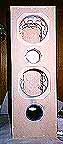
The cabinet was finished with a paper-backed red oak veneer. This veneer is very flexible, is easy to work with and comes in 4' x 8' sheets. But before I veneered, I prepared the cabinets. Using a random orbital sander with 150 grit paper, I sanded the entire cabinet, making sure all adjoining but-end joints were completely flush and the wood filler used for the countersunk screws was flush with the cabinet as well. This was the time when I routed the front baffle side edges. Using a 1/2" radius round over bit with ball bearings, I rounded the sides of the front baffle, leaving the top and bottom squared. This round over was done for two reasons. First, I wanted to use one large sheet of veneer to cover the two sides and front of the enclosure. To do this, the veneer has to be bent. The 1/2" radius allows this to be accomplished without cracking the veneer. Second, sound deflection from the front baffle is minimized using the rounded edges.
My first attempt to veneer the cabinet used contact cement. I veneered the back first. The contact cement was soaked up by the cut ends of the MDF and required 4 coats before I was ready to veneer. Contact cement was applied to the veneer as well, and took only two coats. The upside of using contact cement: the bond is very good and permanent. Waiting time is 20-30 minutes between coats. The downside of using contact cement: the bond is very good and permanent!!! Once the pieces come together, that's it! There's no turning back. It's a done deal. Alignment is difficult, and there is little if any room for error. There are two standard techniques used to help align veneer when using contact cement. Use a slip sheet of wax paper or wrapping paper between the enclosure and veneer. Align the pieces. Pull the paper out about 1/4", and tack down the veneer, making sure it is still aligned properly. Keep drawing the paper down a little at a time while using a J-roller to roll the veneer down. Go with the grain and don't roll over the paper. Continue until the paper is completely removed. Another method is to use 1/4" dowels to separate the veneer from the cabinet. The dowels essentially replace the paper in separating the box from the veneer. Taking one dowel out at a time, follow the same procedure as the slipsheet paper method until all the dowels are removed. In both methods, be sure that the cement is completely dry before attempting to veneer or you will be fishing wax paper or pieces of dowel out of your cabinet / veneer! Aside from all this, the fumes are flammable, noxious, and downright unpleasant! There is a non-flammable contact cement available; however, it is a lot more expensive, and the solvent used (trichloroethylene) is a cancer suspect agent. To add insult to injury, it's a chlorinated hydrocarbon, and we know what we're doing to the ozone layer just to make our cabinets pretty! Not a great alternative, eh? Regardless, if you decide to use contact cement, do it with adequate ventilation.
However, after all this, the back of the cabinet veneered very nicely. No blisters, bubbles, or misalignments. I did, however, catch a slight buzz from the toluene.
Take heart! There is an alternate method you can use. It's the method I used for veneering the rest of the cabinet. It entails yellow carpenter's glue and an ordinary household iron. That's right, an iron! No need for slip sheets, dowels, or gas masks. Here is how I veneered the sides / front using one continuous sheet of veneer.
As I mentioned before, I wanted to veneer the sides and front with one large sheet of veneer. I measured the length of veneer I needed to go from one side, around the front of the cabinet, and back to the end of the other side. I cut the veneer, leaving an overhang of about 1/4" all around. I laid the veneer over the cabinet, making sure that the overhang was equally distributed over all the edges, thus, squaring the piece. I made tick marks on both the veneer and the cabinet to use for aligning the veneer later. I also drew a line around the edges of the veneer for alignment purposes. Then I scuffed up the paper on the back of the veneer using 220 grit sandpaper. This allows the glue to be distributed more evenly. Making sure all saw dust is removed from both the cabinet and veneer, I applied yellow glue to the cabinet and the veneer. I used a very small roller with a short nap. This enabled uniform coverage and made spreading the glue effortless. I worked fairly quickly, leveling the thicker parts of the glue with a rubber spatula. Although the glue is water-based, it does tackify quicker than white glue. For the cabinet, I did one side at a time, waiting for the one side to dry before moving on to the next side. The glue is completely dry when there is no more creamy color present, and the glue gives the appearance of a coat of varnish. Check to see if the cabinet and veneer are completely covered. If the coating doesn't shine, give it another coat. I managed to put the glue on thick enough so one coat was sufficient. Once the glue was completely dry, I propped the cabinet on its back with a couple of 2x4s and positioned the veneer using the lines and tick marks I made. With the iron set on "Cotton", I used the iron tip to tack the veneer into place. Pressing fairly hard (I used two hands), I ironed down the veneer on the front first, working from the center out. I put some heavy-duty aluminum foil on the iron to distribute the heat more evenly. I worked around the 1/2" radius, then on to the sides. I made sure all surfaces were covered and the veneer was glued flat to the cabinet. I check for "crackling" of the veneer, which is an indication that the surfaces are not bonded. Problem areas were gone over if needed. Once the veneer was completely cooled, I used a veneer trimming bit to trim the veneer flush with the cabinet. I then cut the holes for the drivers and port, also with a trimming bit. All the edges around the cabinet were heated with the iron once again to ensure a good bond. I carefully filed the edges, then lightly sanded to give a seamless appearance. Any scuffs or slight discoloration the iron left were scraped off using a SANDVIK cabinet scraper, then sanded with 220 grit sandpaper.
This process may sound like a lot of work, but it is relatively easy and the end result looks impressive. Once the glue is dry you have about 3 days to put the veneer on before the glue begins to cure. However, I found that veneering right after the last bit of water evaporates gives best results. The glue melts more easily, takes less effort, and the bond is stronger. The longest time for this process is spent waiting for the glue to dry. The top and bottom pieces were done the same way, matching the grain as best as possible. The veneered rounded over edges give the appearance that the cabinet is made from a big block of red oak.
At this point the cabinets weighed 45 pounds each, without the drivers and xovers.
Staining / Topcoat
Once the cabinet was veneered, I applied the stain. This is obviously the builder's choice as to how he or she wants to finish the cabinets. The choices are limitless. I used a pickling stain so the speakers would match the furniture we have in our home theater room. This was not my first choice, however, taking into account the S.O.A.F. (significant-other approval factor) I grew to like this finish very quickly! The pickling stain gives the red oak a champagne color . The grain shows as white. I followed the instructions on the can and repeated until I got the desired color and tones I wanted.
At this point I drilled the holes for the mushroom grille fasteners. This procedure is described in The grille.
I used a semi-gloss polyurethane as the top coat. I used 2 coats, lightly sanding with 320 grit sand paper between coats.
![]()
The grille
After talking about early reflections on the front baffle and routing the front to limit this phenomenon from happening, and going through the trouble of flush mounting the drivers, it is ironic to even think about installing grilles on loudspeakers. One would guess that grilles would cause this phenomenon as well. However, in the real world, grilles do have a function (two actually): We must protect those ever-sensitive drivers from screaming rugrats who are just itching to see just how much force it takes from a little finger to puncture those pretty cones! Speakers, especially when finished in the way these speakers are, are pieces of furniture. Speaker grilles are also aesthetically pleasing. The compromise here is to make nice looking grilles that can be easily removed for critical listening.
I wanted the grille to show as much of the veneered front baffle as possible while still covering the drivers and port. I made the grille out of 5/8" particle board. The outside dimensions for the grille frame were 7 3/4" X 23 1/2". I used a 1/2" round over bit to router the sides, top, and bottom of the grille frame. Cutting the holes from the frame was done using a jigsaw. The frame was 3/4" all the way around, and I left a 1/2" cross brace for stability and strength that was positioned between the upper woofer and tweeter. I also left triangular-shaped pieces on all four corners and the brace for added strength. I rough cut the holes, then smoothed the rough edges with a file (see grille frame). I placed both grilles on top of each other and drilled holes through both grilles for installing the mushroom grille fasteners. I did this so the grilles would have the exact same hole configuration so they may be used interchangeably with either cabinet (I plan on removing these grilles often, and I didn't want to have to worry about which grille goes with which cabinet). I positioned the grilles on the cabinets, and using the grille hole as a guide, I continued the hole into the cabinet for installing the mushroom grille fastener to the cabinet.
I spray painted the frame black, then installed the female grille fastener to the cabinet and the male fastener to the grille. I then stretched black grille cloth tightly over the frame and fastened the cloth to the back of the frame with heavy duty staples.
![]()
Putting it all together
With the cabinets finally finished, I was ready to put in the hardware. The woofer xover board was installed behind the lower woofer, and the tweeter xover was installed behind the upper woofer, both on the back wall of the cabinet. The board was fastened using a little yellow glue and #10 /1" brass screws. All the appropriate wires going to the positive and negative terminals of the back cup were connected using ring crimp connectors, and the cup was screwed into the back of the cabinet using standard terminal cup screws. I drilled the pilot holes for the screws with a 3/64" drill bit. I then installed the foam on the back of the cabinet. The foam went over the xovers and extended down to about 1" above the port. I applied some neoprene gasket tape around the perimeter of the driver holes to make the seal between the driver and the cabinet. The drivers were placed in their respective holes in the cabinet, and pilot holes were made using a 7/64" drill bit. Be very careful when drilling the holes to avoid damage of the drivers. I then removed the drivers, and all the wires to be connected to the drivers were snaked through their appropriate hole in the front baffle. I then filled each cabinet with about 1/4 pound of polyester batting. This material can be lofted about 1 inch or so. I fluffed it behind the woofers and tweeter, so that the foam, the speaker wires and braces kept it in place so as to not let it drop down and interfere with the port The drivers were wired using silver solder as described in The crossover section. Tinning driver terminals is recommended here. I used 14 gauge silver-coated wire for all my interconnections.
* Note: Be careful not to overheat the terminals on the drivers, especially the tweeter. The tweeter flange is only plastic. Use just enough heat to melt the solder, then remover the soldering iron. Check the connections once everything cools.
I carefully dropped the drivers in the cabinets and fastened them using #8/ 1 1/2" (woofers) and #8/1" (tweeters) black panhead screws, being careful not to puncture the drivers, especially considering the drivers are 60% of the cost of this project! The final weight of the cabinet finished with drivers and xovers.........55 pounds each. (see finished project )
![]()
The stands
A good quality bookshelf speaker (like the Audax A652) deserves a good stand in order to position them properly for listening (the tweeter should be ear level when seated) and to transfer cabinet vibrations to the floor. I made a pair of speaker stands out of some left over 3/4" MDF and 3/4" X 4" red oak hardwood. The tops were cut 8" X 10" and the bottoms were cut 12" X 12". The red oak pillars (2 for each stand) were 20" long. For cosmetics, the top and bottom piece were routed on the edges using a 3/8" beading bit. The red oak pillars were routed with a 1/2" radius round over bit on the outside front face only. The top and bottom pieces were spray painted glossy black. The red oak pillars were stained with pickling oak stain to match the speakers, and topcoated with semi-gloss polyurethane.
The red oak pillars were centered on the top and bottom of the stand, toed in slightly at 20 degrees, and installed using countersunk #10 1 1/2" stainless steel wood screws, three per joint. The top was inverted so the routed piece was facing the floor. Spikes were installed on the base. A small triangle of high density foam was put on all corners of the top piece. Including the spikes, the overall height of the stand was 22 1/2". Here is a picture of the (stands).
![]()
The sound
What can I say about the sound? Evaluating a loudspeaker's performance can be very subjective. Sure, there are ways to measure frequency response over a given range (typically 20 Hz - 20 kHz). There are also ways to measure the distortion of a loudspeaker at different frequencies. On paper, a speaker may look like a real winner, but realistically, everyone's personal taste comes into play. As I mentioned before, some like the up-front sound of metal dome tweeters. Others like a lot of boomy bass. Still others prefer an accurate and tight mid-range and mid-bass. Since we all don't have "golden ears", we must rely on what our ears are telling us. IMO however, it is preferable to start with a speaker that has a flat response, regardless of the speaker's sonic signature. In the case of the A652, ± =B1 2 dB between 60 Hz and 20 kHz is pretty flat.
All listening was done with the grilles removed and subwoofer turned off. Before really sitting down and giving a careful listen, I allowed the drivers a break-in period where I played varying types of music for several days. The gear I used for the listening tests included a B&K AVP2000 preamp, B&K AV5000 power amp (105 watts X 5), and Pioneer CLD-D703 combi player. Interconnections were Monster and 12 gauge speaker wire. For movie soundtracks, I included a Paradigm CC-300 center channel speaker and a pair of Paradigm ADP-150 adapted dipole surrounds. The A652s were placed on the custom-made 22 1/2" stands, and were toed in so they were facing outward slightly from the primary listening position. Listening material included an eclectic selection of both audio CDs and movie laser discs. For CDs, the combi player was put in the CD direct mode (shuts off the video circuitry) and the preamp was set to Direct mode (bypasses the processor). For movie soundtracks, the processor was set to Dolby Pro Logic. The set up was calibrated using the AVP2000 pink noise generator to 85 dB at the primary listening position using a SPL meter set to C weighting.
If I had to use one word to describe these speakers, it would be......accurate. The speaker's forte is its mid-range and mid-bass...very tight, detailed, with a lot of punch. Every instrument could be picked out without being too up front or overbearing. The tweeter exhibited soft, yet detailed highs. There was no brightness to it at all. In the first movement of Mozart's string quartet piece The Hunt, every instrument was clearly identifiable, emitting a crisp, lively sound. Imaging was excellent both in stereo and in DPL mode, and there was very little coloration in the mid-range (the human ear's most sensitive frequencies). On Donald Fagen's Teahouse on the Tracks, I could pick out background sounds and instruments I hadn't heard before. I did notice that the A652s would not make a less than stellar recording sound exceptional. Disney's laserdisc Fantasia , recorded in 1940, sounded very good but not great. For all you home theater fans, you'll be pleased to hear that these speakers are T-2 and T-Rex approved. Played at reference levels with the proper bass management (80 Hz high pass cutoff), there was no sign of strain or distortion. Although these speakers sound great alone, they will not reach down to the bottom octave. So, anyone with a craving for deep bass would be advised to use them with a sub.
Do I like these speakers? Absolutely! I've found that they can perform equally as well in a two-channel or home theater setup. As usual, placement and gear used will play a big part in how any speaker will perform.
![]()
Cost analysis
The cost of the drivers was $300.00, purchased from Zalytron. The cost of the xover parts was $80.00; the inductors and resistors were purchased from NCMS and the caps from Just Speakers. As in any DIY project, the driver and xovers contribute to a big chunk of the overall cost.. The other components combined cost approximately $75.00. Bear in mind that the cost of lumber, veneer, hardware, etc., is very region-specific, so your mileage may vary. The total cost of the stands was $35.00.
Was this project worth the money? You bet it was! IMO, if one were to buy a commercial speaker of this quality, it would cost 3-4 times the price. Labor, of course, is not considered in the cost estimate.
![]()
Tools
I do not have a professional woodworkers shop. The only power tools I used for this project were a router, a jigsaw, a random orbital sander, a belt sander, a reversible electric drill, a circular saw, and a table saw. The table saw I used belonged to a friend's dad.
Future work
My next project will be a pair of subs based on the NHT 1259, the bass driver NHT uses in their flagship 3.3 and their SW-3P subwoofer. They will be finished in the same manner as the A652s. Since these enclosures will be about 3 ft3, they will most likely replace my end tables!
![]()
Acknowledgments
I would like to thank all the people who have helped me make this project such a success, in particular, Bill Eckle, Dan Kerl, North Creek Music Systems, my wife Sharon for all her support, Leo Fitzgerald and his dad for the use of the table saw, and many of the subscribers to the DIY Loudspeaker and Related Topics list who are too many to name.
![]()
Bibliography
"Kit Plans: Build Your Own
Loudspeakers";
Audax of America
10 Upton Drive
Wilmington, MA 01887
Phone (508) 658-0700
Fax (508) 658-0703
"Wiring Guide"
Copyright 1995
North Creek Music Systems
Main Street, P.O. Box 1120
Old Forge, NY 13420
(315) 369-2500
"Cabinet Handbook"
Copyright 1992
North Creek Music Systems
Main Street, P.O. Box 1120
Old Forge, NY 13420
(315) 369-2500
"The Loudspeaker Design Cookbook"
Fifth Edition
by Vance Dickason
Audio Amateur Press Publishers,
Petersborough, New Hampshire
Copyright 1995
![]()
© Copyright 1995, 1996, 1997
Secrets of Home Theater & High Fidelity
Return to Table of Contents for this Issue.
Magazine Publishing Solutions by