Driver Description
I removed the driver, and noted it was secured with machine screws and
inserts. This is a nice touch; most woofers are secured with wood screws.
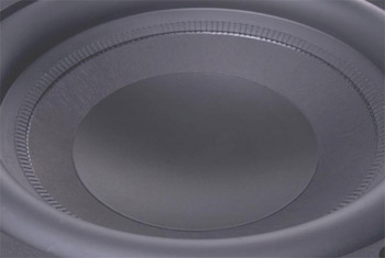
The UFW-12 woofer features beautiful components and a high level of fit and
finish. Thoughtful touches abound like a hand-stitched surround, machine
screws anchoring the spiders, black wrinkle finish paint on the basket,
chrome plated top and back plates, and metal screening around the base of
the basket and covering the vent.
 The
woofer has the following performance features:
The
woofer has the following performance features:
● 3" aluminum voice coil with aluminum former
● 12 spoke aluminum die-cast basket allowing for high excursion
● Double-stacked 200 ounce magnet assembly
● 50 mm vented pole piece
● Multi-layer Kevlar impregnated honeycomb cone for extreme rigidity
● Hand-stitched Santoprene rubber surround
● Dual mirrored spiders with opposing silver plated cadmium copper tinsel
leads
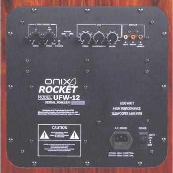
Amplifier Description
●
Class G (1,000 watts continuous into 4 ohms)
●
Phase Control (0/180 two-way slider switch)
●
Single Band PEQ (frequency, Q, level –14.5 dB to +6 dB)
●
Clipping, Thermal, and Overload Protection Limiter (red warning light)
●
Off On/Auto (two-way rocker with green standby and yellow operating light)
●
Gain/Volume Control
●
Low Pass Filter (30-200 Hz, continuously variable, 4th order)
●
High Pass Filter (23 Hz, 10th order, non-user adjustable)
●
Low Level L/R RCA inputs (connected to low pass filter)
●
Low Level LFE Direct RCA input (bypasses low pass filter)
●
Detachable Heavy Duty Power Cord (3 prong) with 10 amp GMA fuse block
 This
amplifier is Class G, which consists of a single class AB output stage that
is connected to two power supply rails by a switching device. Most of the
time, the amplifier will run off the lower voltage power supply rails. But
when high power output is needed, the output stage will automatically switch
to the higher voltage power supply rails. This improves the efficiency of
the amplifier and allows cooler running conditions. The switch between the
two power supply rails is so fast that it cannot be detected under normal
listening conditions.
This
amplifier is Class G, which consists of a single class AB output stage that
is connected to two power supply rails by a switching device. Most of the
time, the amplifier will run off the lower voltage power supply rails. But
when high power output is needed, the output stage will automatically switch
to the higher voltage power supply rails. This improves the efficiency of
the amplifier and allows cooler running conditions. The switch between the
two power supply rails is so fast that it cannot be detected under normal
listening conditions.
I liked the three-color single operating light. Green indicates standby,
yellow indicates normal operation, and red indicates limiter activity. The
red limiter light is an effective means to inform owners the subwoofer is
being overdriven.
The LFE Direct input bypasses the low-pass filter, and should be used
whenever digital bass management is being performed by your SSP or receiver. The L/R
inputs are linked to the low-pass filter control, and would typically be
used in a stereo application where the SSP lacks digital bass
management. Users should be aware that the LFE Direct input provides a 6 dB
higher output level than either the L or R input. This is by design, since
the use of both the L and R inputs in a stereo application will sum to the
same output level as the LFE Direct input.
 The
owner's manual provides an in depth description of how to operate the PEQ.
The single band on-board PEQ features three continuously variable controls:
Bandwidth (Q = 0.1-1.0), Frequency (18-80 Hz), and Level (-14.5 to +6 dB).
Essentially, this control can be used to tame a peak or boost a low area in
the in-room frequency response.
The
owner's manual provides an in depth description of how to operate the PEQ.
The single band on-board PEQ features three continuously variable controls:
Bandwidth (Q = 0.1-1.0), Frequency (18-80 Hz), and Level (-14.5 to +6 dB).
Essentially, this control can be used to tame a peak or boost a low area in
the in-room frequency response.
It should be noted that there is a difference between a relative low spot in
the FR curve and a true room null. A relative low can be boosted, but a true
room null cannot. Attempting to boost a true null will only reduce amplifier
headroom and stress the subwoofer. True nulls are best addressed by
experimenting with subwoofer placement and different listening positions,
and employing bass traps.
Click Here to Go to Part IV.